
5V regulator circuit

The 5V regulator circuit typically employs a linear voltage regulator or a switching regulator topology to achieve the desired output voltage. In a linear regulator configuration, the circuit uses components such as a pass transistor, resistive feedback network, and bypass capacitors to maintain the output voltage at 5V. The input voltage, which can vary between 10V and 20V, is fed into the regulator, where the excess voltage is dissipated as heat, making thermal management a consideration in the design.
For improved efficiency, especially in applications where power dissipation is a concern, a switching regulator may be utilized. This type of regulator operates by rapidly switching the input voltage on and off, using an inductor and a diode to store and release energy, thereby minimizing power loss. The output voltage is regulated by adjusting the duty cycle of the switching signal.
In both configurations, the circuit may include additional components such as input and output capacitors to filter out noise and stabilize the voltage levels. The choice between a linear and switching regulator depends on the specific application requirements, including load current, efficiency, and thermal performance.
Overall, the 5V regulator circuit is essential in various electronic applications, providing a reliable and stable power supply for microcontrollers, sensors, and other low-voltage devices.5V regulator circuit Is 5v regulator circuit, the circuit consists of a 5v voltage 10-20V DC power, low-power self-consumption and high efficiency.
Related Circuits
The two circuits below illustrate the application of the 555 timer to activate a relay for a specified duration by pressing a momentary normally open (N/O) push button. The circuit on the left can be used for longer time...
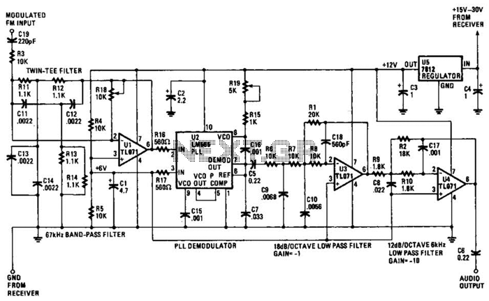
The operational amplifier (Op Amp) U1 and its associated components form a 67-kHz bandpass filter. A twin-T network, consisting of four 1100-ohm resistors and four 0.0022-microfarad capacitors, is integrated into the feedback loop of the op amp. This configuration...
The objective is to enhance information transmission through the use of articles. Please contact us via email at [email protected] within 15 days if there are any issues related to article content, copyright, or other concerns. Prompt action will be...

The schematic for this project is designed to be very simple, utilizing a minimal number of components to keep costs and assembly time low. The primary components in the schematic include the PIC 18F452 microcontroller, a tilt sensor, and...
The circuit of an FM Tracking Transmitter Circuit or Remote Control Transmitter Circuit is explained using a 555 IC and 2N4392 transistors. The FM Tracking Transmitter Circuit utilizes a 555 timer integrated circuit (IC) configured in astable mode to generate...
This project has two features. It will let you know when a single phone is using the line and also when two phones are on the line! The green LED indicates the first phone and the red LED indicates...