
Ir Receiver Circuit

The described IR receiver circuit typically consists of a few essential components: an infrared photodiode or phototransistor, a resistor, and an operational amplifier or a simple transistor for signal amplification. The photodiode detects infrared light emitted by a remote control or other IR source. When exposed to IR light, the photodiode generates a small current, which is then passed through a resistor to develop a voltage signal.
To enhance the sensitivity and range of the circuit, a transistor may be used as an amplifier. In this configuration, the photodiode is connected to the base of the transistor, which is powered by the 9-V battery. The collector of the transistor is connected to the load, which could be an LED or another output device.
The layout of the circuit is not critical, allowing for flexibility in design. However, it is important to keep the connections short to minimize noise and ensure reliable operation. The choice of components, particularly the photodiode or phototransistor, can affect the circuit's performance, including its response time and sensitivity to different wavelengths of infrared light.
Overall, this simple IR receiver circuit is an excellent project for beginners in electronics, providing a practical application of basic principles in photonics and signal amplification. The long-lasting 9-V battery ensures extended use, making it suitable for various applications such as remote control systems, wireless data transmission, and sensor networks. This circuit is just about the simplest IR receiver you can build. The parts are cheap, the layout is not critical, and a 9-V battery will last a long time.
Related Circuits
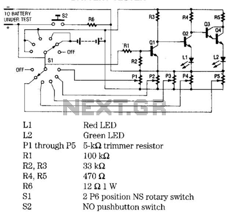
The battery tester utilizes four transistors and two LEDs to indicate the status of any battery being tested. Transistors Q3 and Q4 are configured in a Darlington arrangement, providing extremely high gain. LED L2 illuminates when a small positive...
The development of the entire system necessitated a thorough identification of all processes related to the laser controller. The initial diagram outlines the primary physical components utilized in the CNC laser system. The setup includes a power supply, a...
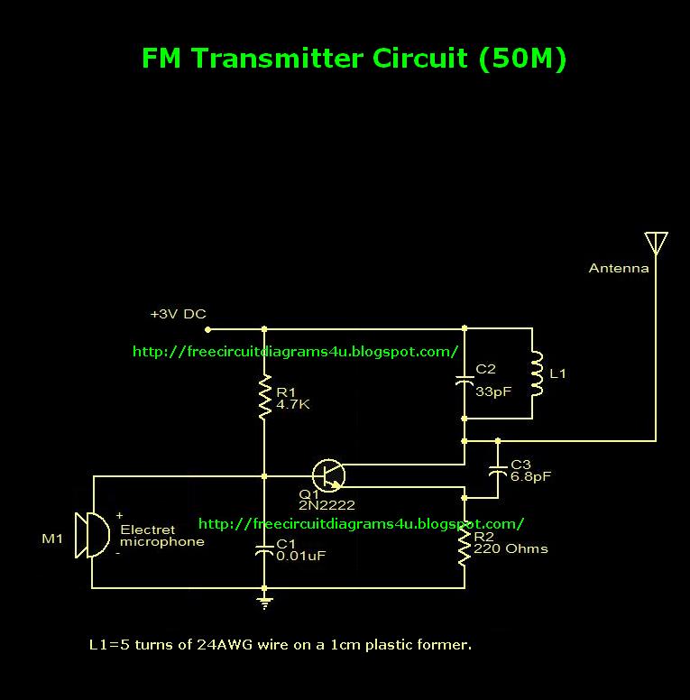
This is an FM transmitter circuit diagram. This circuit uses a 2N2222 transistor, allowing it to operate at 3V and transmit signals up to 50 meters. The FM transmitter circuit consists of several key components, primarily centered around the 2N2222...
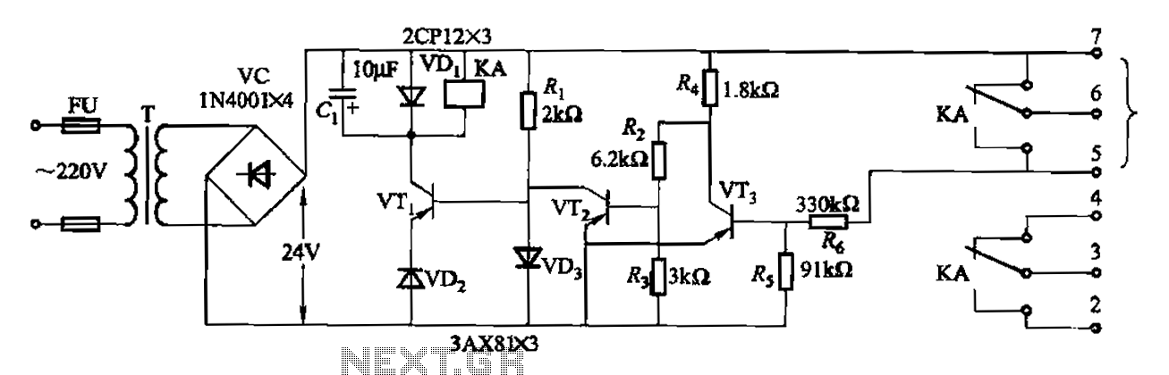
Another JYB type liquid level controller internal circuit is shown. This circuit employs a Schmitt trigger configuration, enhancing the reliability of the action level controller. The JYB type liquid level controller utilizes a Schmitt trigger circuit composed of transistors VT2...
In the second equalization circuit connection method, it operates as illustrated in Figure 1-96. When the potentiometer wiper is moved to the inverting input terminal "a", the resonance impedance of the parallel combination of the feedback resistor RB reaches...
This simple circuit combines two or more audio channels into a single channel (for example, converting stereo to mono). The circuit is capable of mixing any number of channels and operates with minimal power consumption. While the schematic illustrates...