
led interfacing with spartan 3 primer

The Spartan-3 board is designed to facilitate various electronic projects, utilizing a field-programmable gate array (FPGA) for flexible hardware configuration. The eight LEDs serve as visual indicators or outputs for the logic implemented within the FPGA. Each LED is connected to a dedicated I/O pin on the FPGA, allowing for individual control.
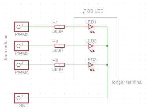
The connection configuration includes a 330-ohm resistor in series with each LED, which serves to limit the current flowing through the LED. This resistor is crucial for preventing damage to the LED due to excessive current. The cathodes of the LEDs are tied to the ground, establishing a common reference point for the circuit.
To activate a specific LED, the corresponding FPGA I/O pin must be set to a high state (logic level '1'). This action forward-biases the LED, allowing current to flow from the power supply through the LED and the resistor to ground, thus illuminating the LED. The brightness of the LED can be controlled by adjusting the duty cycle if a pulse-width modulation (PWM) technique is implemented within the FPGA logic.
In summary, the Spartan-3 board's LED configuration provides a straightforward method for visual feedback in digital designs, demonstrating the capabilities of FPGAs in controlling output devices through simple logic states. This setup is essential for prototyping and testing various electronic applications, enabling engineers to observe the results of their designs in real-time.The Spartan-3 board has eight LED Connected with FPGA I/O pins (details tabulated below). The cathode of each LED connects to ground via a 330 © resistor. To light an individual LED, drive the associated FPGA control signal to High. 🔗 External reference
Related Circuits
This evening, after returning home from a paragliding appointment, there was a realization that the RGB LED driver code written the previous day needed improvement. The code was refined and annotated extensively for educational purposes. Although the current skill...

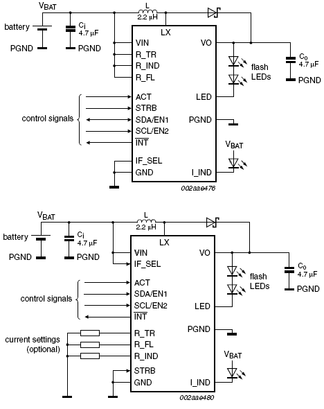
An ultralow dropout current source maintains accurate LED current at very low ILED voltages. Automatic mode switching optimizes efficiency by monitoring the voltage across the LED current source and switching modes only when ILED dropout is detected. The LTC3216...
This device offers an extended battery life and operates with low power consumption. Additional features include battery and LED overload protection, seamless operation with safeguards against overtemperature, overvoltage, a timeout function, undervoltage lockout, and feedback short-circuit protection. The device is...

In various electronics-level adjustments, such as LED drivers for LCD panel backlight controls, the AD5228 can be utilized. A manually adjustable LED driver is illustrated. The AD5228 is a dual-channel, digitally controlled potentiometer (DCP) that can be employed in applications...

A Coil Coupled Operation Metal Detector made from readily obtainable components and using an ordinary medium receiver as a detector. The metal detector shown here may well represent a new genre. At any rate, after some exposure, it is...

The circuit illustrated briefly flashes an LED to attract attention and remains illuminated as long as power is supplied. The circuit utilizes the well-known 555 timer integrated circuit (IC) configured as a standard astable multivibrator with resistors RA, RB,...