
Manual Adjustable LED Driver
The AD5228 is a dual-channel, digitally controlled potentiometer (DCP) that can be employed in applications requiring precise control over electrical signals. It features a 256-position wiper setting, allowing for fine-tuning of output levels, which is particularly useful in LED driver circuits for backlighting applications. The device operates via a simple two-wire interface, enabling easy integration with microcontrollers or other digital systems.
In a typical application, the AD5228 can be configured to adjust the brightness of an LED by varying the resistance in the circuit. The LED driver circuit can consist of a power supply, the AD5228, and the LED itself. The output from the AD5228 is connected to the LED, controlling the current flowing through it based on the wiper position selected via the digital interface. This configuration allows for smooth dimming capabilities and precise control over the LED brightness, which is essential for enhancing user experience in LCD displays.
Additionally, the AD5228 supports both linear and logarithmic taper options, providing flexibility in response characteristics based on application needs. The device also has built-in EEPROM functionality, allowing for the storage of settings and configurations, which can be particularly beneficial in applications where consistent performance is required after power cycling.
To implement the AD5228 effectively in an LED driver circuit, careful consideration must be given to the power ratings, the maximum allowable current through the LED, and the overall thermal management of the circuit to prevent overheating. Proper layout practices, including adequate grounding and minimizing parasitic capacitance, will enhance the performance and reliability of the circuit.In many electronics-level adjustments such as LED drivers for LCD panel backlight controls, we can use AD5228. A manually adjustable LED driver is shown on.. 🔗 External reference
Related Circuits
Flashing frequency can be varied by changing R1 value in the 1M - 4M7 range. This circuit is very efficient when driving a small 3.2V incandescent lamp. In this case omit the LED and R3, connecting the bulb across...
The number of pulses at the input can be visually confirmed by connecting a light-emitting diode to the output of the counter. In this circuit, a counter is utilized to count the number of input pulses. The output of the...
The circuit was designed to provide an adjustable power supply that is symmetrically configured, offering a voltage range from 1.25V to 30V at a current output of 1A. The adjustable power supply circuit is typically composed of several key components...
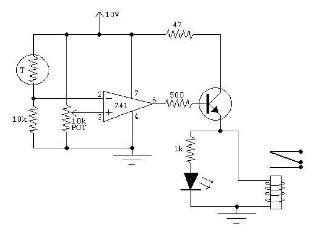
There is no prior experience in building controllers, and there is uncertainty about how to begin. A budget constraint of less than 100 euros is present. A power thyristor is already available. The inquiry revolves around the best method...
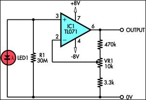
This circuit demonstrates the use of a standard LED as a light sensor. It utilizes the photovoltaic voltage generated across the LED when exposed to light. LEDs are more cost-effective than photodiodes and feature an integrated filter, which is...
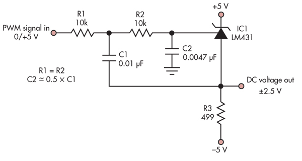
This simple circuit converts a 5V PWM signal into a variable precision reference voltage with a range of -2.5V to +2.5V. Many designs, such as a digitally controlled power supply or a programmable dummy load, require a Digital to...