
LED level meter driver IC Fig.
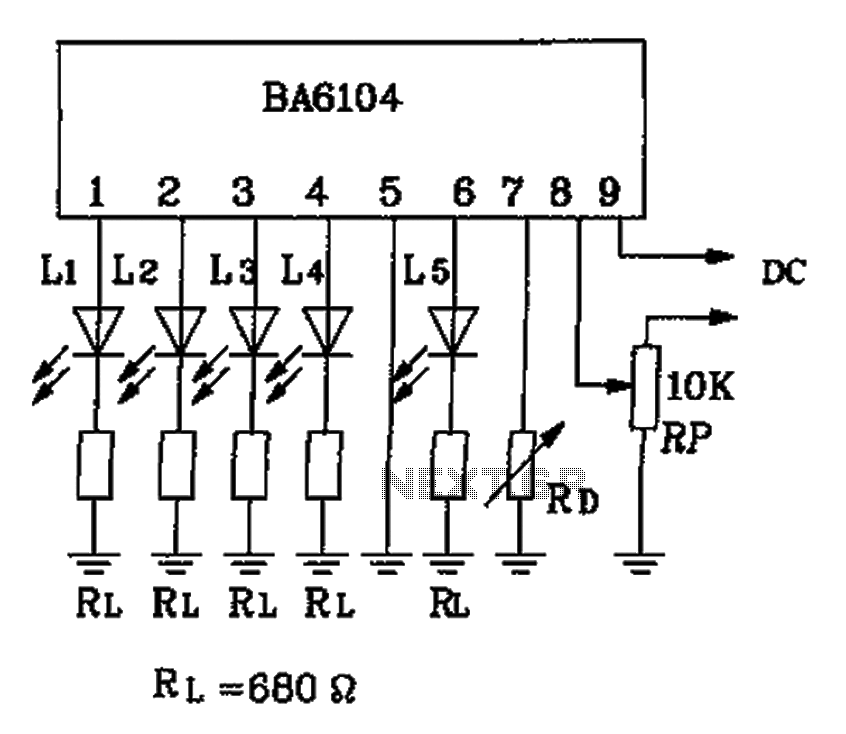
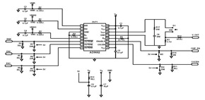
The BA6104 IC is designed to drive a five-digit LED display, providing a visual representation of signal levels in various electronic applications. Its operation is based on the input voltage level, which is monitored and compared to a predefined threshold. When the input voltage surpasses the threshold of 1V, the circuit activates the display, illuminating the appropriate segments of the LED display to indicate the level.
The reference voltage (Vref) is a critical parameter in this circuit, as it determines the sensitivity and accuracy of the level measurement. The relationship provided indicates that Vref is influenced by the power supply voltage (Vcc) and the resistance (R) connected to the circuit. Specifically, as resistance increases, Vref also increases, thereby affecting the display output. This relationship can be utilized to calibrate the circuit for specific applications, allowing for adjustments based on the required input voltage range.
In practical implementations, the circuit may include additional components such as capacitors for smoothing the power supply and ensuring stable operation, as well as other passive components that may be necessary for signal conditioning. Proper layout and component selection are essential to minimize noise and ensure accurate level readings. The BA6104 IC is suitable for use in audio level meters, signal processing equipment, and other applications where visual level indication is beneficial. As shown is BA6104 Five-digit LED level meter driver IC basic application circuit if the level is higher than required to display 1V, only 7 feet in the power supply Vcc indire ct a resistance R, the Vref will rise to their relationship as: Vref [Vcc + 0.75R (k )]]/[0.75R (k ) +1].
Related Circuits
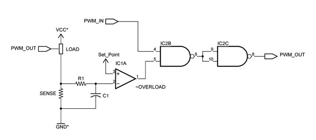
This chapter was removed from Applied Robotics 2 due to space constraints. It addresses general motor control issues and details the construction of a 5-amp motor driver. The principles discussed can be applied to larger motor controllers. Although commercially...

Often the need to control light switch on the instrument. If napájíme LED source of low DC voltage sufficient to classify a series of LED-resistor of appropriate resistance. Another situation occurs, if a small supply available, or to indicate...
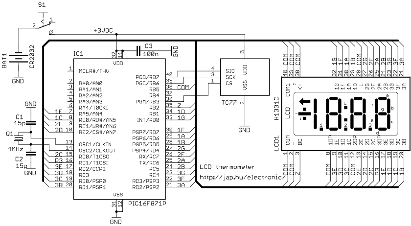
The circuit drives the LCD pins with 50% square waves. Each segment on this LCD is connected to the COM backplane and a separate pin. When a pin is driven in phase with the COM pin, the corresponding LCD...
The receiver circuit and display module will receive the high-frequency AC power cord and decode it to provide actual temperature readings using digital IC No. CD4553 (Three-digit BCD Counter IC) and IC CD4511 (BCD-to-7-Segment Latch/Decoder/Driver IC). The frequency pulses...
This schematic was created using a 2-layer evaluation board for the AD9662 3-Channel Laser Diode Driver. This device is primarily utilized in high-performance CD-DVD recordable drives and for laser diode current switching. The AD9662 is a specialized integrated circuit designed...
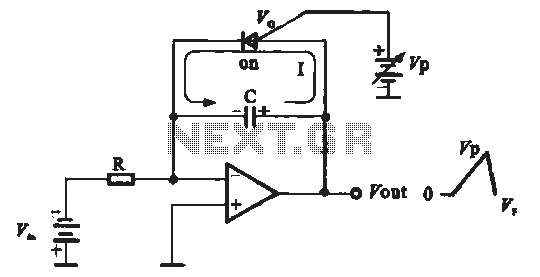
A sawtooth voltage-controlled oscillator operates by first generating a negative potential maximum at the output of the comparator. This output is then fed to the inverting input terminal through resistor R1, which is part of the relaxation oscillator. The...