
LM35 Digital Remote Thermometer circuit and explanation
The described circuit functions as a temperature measurement and display system that utilizes digital electronics for precise readings. The high-frequency AC signal is first isolated to prevent any potential damage to sensitive components. The use of capacitors and inductors ensures that only the desired frequency range is amplified, while diodes serve to protect against voltage spikes.
The digital counting and decoding process is facilitated by the integration of the CD4553 and CD4511 ICs. The CD4553 serves as a BCD counter, which counts the incoming pulses and converts them into a binary-coded decimal format. The CD4511 then translates this BCD output into a format suitable for display on a 7-segment display, allowing for easy reading of temperature values.
The filtering stage, using capacitor C5, ensures that the signal is clean and free from noise, which is critical for accurate measurements. The time base generator (IC4) is essential for creating a stable timing reference, enabling consistent operation of the entire circuit. The division of the frequency signal allows for scaling the input frequency down to a more manageable level for temperature representation.
The final output is displayed through multiplexing techniques, where the three anodes are activated in sequence, ensuring that the display is dynamic and can show the required temperature readings effectively. This multiplexing is controlled by the frequency determined by the previously mentioned components, ensuring that the display updates at a rate that is visually perceptible to the user.
Overall, this circuit design exemplifies a robust method for converting high-frequency AC signals into readable temperature data, demonstrating the integration of various electronic components to achieve a specific measurement goal.For the receiver circuit and display modulewill receive the high frequency AC power cordand decode out to be the actual temperature figures with digital IC No. CD4553 Three-digit BCD Counter IC) and IC-CD4511 (BCD-to-7-Segment Latch / Decoder / Driver IC). The frequency pulses from the wall and safely isolated by C1, C2 and L1 are amplified by Q1 , diodes D1 and D2 of the peak limit his admission. The pulses are filtered by C5, IC1b square, divided by 10 in IC2B and sent for final countdown clock input of IC5. IC4 is the time base generator: it provides IC1b and reset pulses to the making and IC5 locks and opening time of IC5 at 1Hz frequency.
It is powered by a 5Hz square wave obtained from the frequency 50Hz sector Retrieved from T1 secondary, squared and divided by 10 in IC1C IC2A. IC5 readers across the cathodes scenes Q2, Q3 and Q4 with a rate determined by frequency multiplexing C7.
Readers also shows three anodes in parallel by the BCD to 7 segments decoder IC6. In summary, the input pulse power on, say, 2kHz frequency be divided by 10 and displayed as 20. 0 ° C 🔗 External reference
Related Circuits
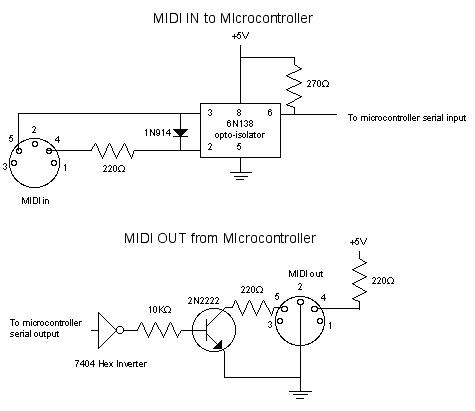
MIDI, or Musical Instrument Digital Interface, is a specification for a communications protocol between digital synthesizers and other digital music devices. It was developed to be as simple and general as possible, providing synthesizer manufacturers with significant flexibility while...
When a key is pressed, the remote control transmits a preamble followed by 32 bits of information encoded using specific pulse timings. The pulse examples can be observed in logic analyzer screen captures, although some glitches are present due...

A GdS cell serves as one leg of a bridge circuit. Potentiometer R6 in another leg establishes the trip point. Potentiometer R5 allows for hysteresis adjustment to prevent chattering or hunting of the relay. The light level must increase...
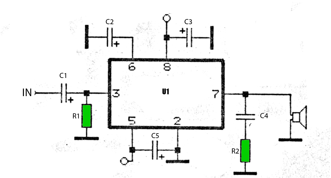
The car power amplifier utilizes the SI1050GL integrated circuit (IC) as the primary amplification component. It delivers an output power of 50 Watts at an 8-ohm mono impedance. The amplifier operates with a DC voltage of up to 25...
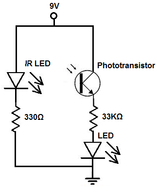
There are two methods to construct a proximity detector. The first method involves mounting the infrared (IR) LED and the phototransistor so that they face each other. In this configuration, the infrared light emitted by the IR LED is...
The circuit consists of two synchronized multivibrators formed by a pair of 555 timer circuits. It is capable of generating two synchronized pulse signals, with the spacing and frequency adjustable by modifying the time constant. The circuit offers flexibility...