
LED Light Flasher Project

The circuit design comprises a 74C04 Hex Inverter IC, which contains six independent inverters. In this application, only one of the inverters is used to create an oscillating signal. The output of the inverter toggles between high and low states, producing a square wave with a specific frequency determined by external components.
To establish the oscillation frequency, a resistor-capacitor (RC) timing circuit is connected to the inverter. The resistor (R) and capacitor (C) values can be adjusted to change the frequency of the output square wave. Typically, a higher resistance or capacitance will result in a slower flashing rate, while lower values will cause the LEDs to flash more rapidly.
The output from the inverter is connected to the anodes of the two LEDs, while their cathodes are connected to ground. The alternating high and low output from the inverter causes one LED to turn on while the other turns off, and vice versa, creating a flashing effect. Current-limiting resistors should be included in series with the LEDs to prevent excessive current from damaging them.
Powering the circuit requires a suitable DC voltage source, typically in the range of 5V to 15V, depending on the specifications of the 74C04 IC and the LEDs used. The circuit can be built on a breadboard for prototyping or designed onto a printed circuit board (PCB) for more permanent applications.
This LED flasher project serves as an excellent introduction to basic electronics concepts, including the use of logic ICs, timing circuits, and LED operation. It can be further expanded by incorporating additional features, such as variable flashing rates or the use of multiple LEDs in different configurations.This simple LED Light flasher project uses a Hex Inverter 74C04 IC to generate a square wave pulse which is used to alternately ON and OFF two LEDs 🔗 External reference
Related Circuits

External circuit converts bass beat of music into pulses. The motor is controlled by them. If there's bass beat recognized then the motor rotates one direction (in full stepping) for a predefined time then stops. If the second beat...

Q1 senses infrared radiation from heat sources, which causes U1 to switch on, activating optocoupler U1 and triggering TRIAC TR1. This controls a fan. The TRIAC can be sourced from Radio Shack or a 200-V, 6-A unit (C106B) can...
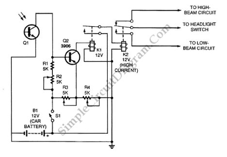
Automatic headlight dimmer circuit diagram for your car's headlight. It ensures safety by providing maximum brightness for the farthest visibility while automatically switching. The automatic headlight dimmer circuit is designed to enhance driving safety by adjusting the brightness of vehicle...
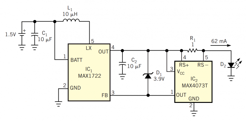
Although white LEDs are common in a variety of lighting applications, their 3 to 4V forward-voltage drop makes low-voltage applications challenging. Charge pumps and other ICs are available for driving white LEDs, but they generally don't work with the...
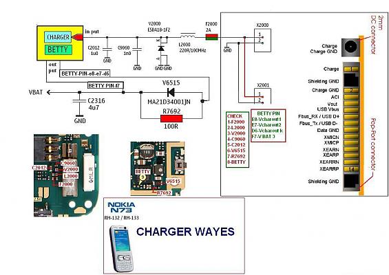
The display lights issue on the Nokia N73 can arise from various factors, such as a broken path in the display circuit or damage to the display driver, among others. This mobile repair guide offers pictures related to the...
This project is also an essential part of the expandable analyser to be published soon or perhaps eventually, and one meter circuit is used for each frequency band. There are many other uses for a simple LED VU meter....
Warning: include(partials/cookie-banner.php): Failed to open stream: Permission denied in /var/www/html/nextgr/view-circuit.php on line 713
Warning: include(): Failed opening 'partials/cookie-banner.php' for inclusion (include_path='.:/usr/share/php') in /var/www/html/nextgr/view-circuit.php on line 713