
LED Audio VU Meter
The described circuit functions as an LED VU meter, which provides visual feedback of audio signal levels across different frequency bands. This versatility allows it to be employed not only in audio mixing environments but also in amplifiers and preamplifiers, where monitoring signal strength is crucial. The design utilizes a single integrated circuit (IC) along with a minimal number of discrete components, making it efficient and cost-effective for various applications.
The circuit features two rectifier stages, which serve to convert the AC audio signals into DC levels that drive the LEDs. This arrangement ensures that the LED indicators provide a responsive visual representation of the audio signal's amplitude, allowing users to gauge levels accurately. The rectifiers are designed to minimize filtering, which enhances the responsiveness of the LEDs to rapid changes in signal level, making it particularly useful for dynamic audio signals.
The schematic likely includes connections for the input signal, power supply, and output to the LEDs. The IC may be responsible for processing the incoming audio signal and controlling the corresponding LED outputs based on the detected signal levels. The discrete components may include resistors and capacitors that help set the gain and response characteristics of the circuit, ensuring that it operates effectively across the intended frequency range.
In summary, this LED VU meter circuit is a practical solution for real-time audio level monitoring, making it an essential tool in any audio engineer's toolkit. Its straightforward design, based on proven application notes from National Semiconductor, ensures reliability and ease of integration into various audio systems.This project is also an essential part of the expandable analyser to be published soon (or perhaps "eventually"), and one meter circuit is used for each frequency band. There are many other uses for a simple LED VU meter. They are ideal as power meters on amplifiers, can be used with mixers (including the high quality mixer described in the project pages), preamps and any other application where it is important to know the signal level.
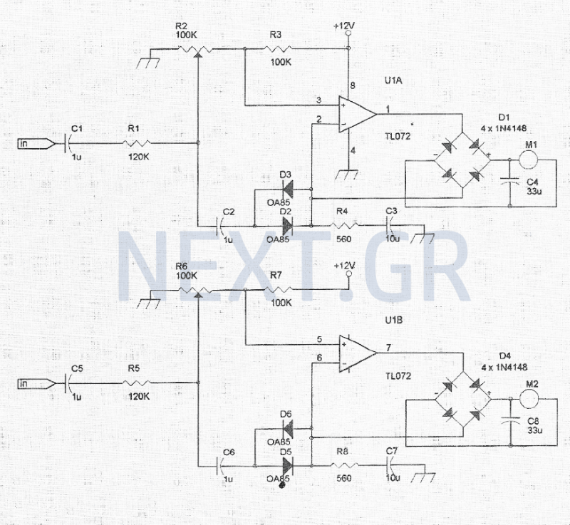
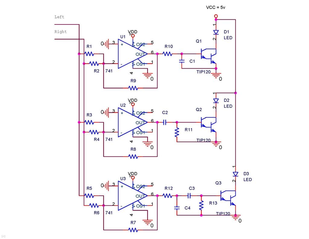
The circuit is completely conventional, and is based on the application notes from National Semiconductor. The circuit is shown in Figure 1 and as you can see it uses a single IC and a few discrete components.
There are two rectifier circuits so that the DC to the LEDs is almost unfiltered. 🔗 External reference
Related Circuits
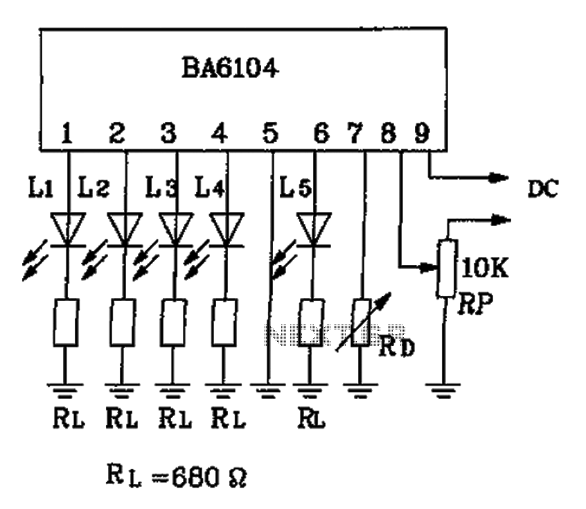
The BA6104 is a five-digit LED level meter driver integrated circuit (IC) used in basic application circuits. When the input level exceeds the required display threshold of 1V, only 7 feet of the power supply Vcc are indirectly affected...
The VU meter is categorized into two types: those that use needle instruments and those that employ LED columns. A VU meter sound level meter is essential for both tube amplifiers and integrated amplifiers. Currently, there are numerous integrated...
This circuit can drive analog moving coil meters, for use as a VU meter. The circuit is left connected to the line terminals of the amplifier. The VU meter works pretty simple. T1 and T2 signal increase. The signal...
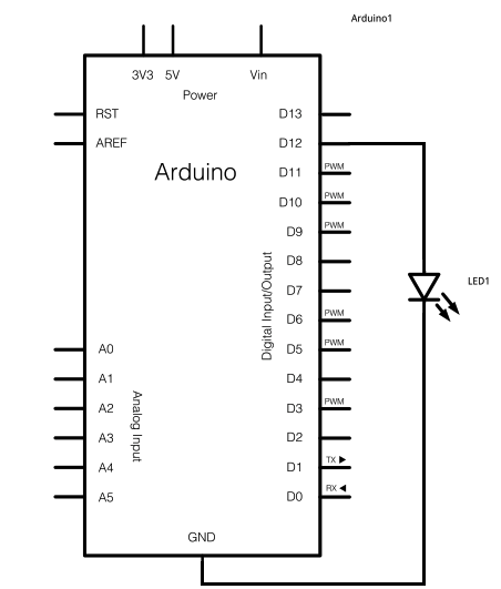
The schematic for this project consists of adding a single 5mm LED to one digital output port on the Arduino. The main components in the schematic include the Arduino Uno, a 5mm LED, and a USB cable. The left...
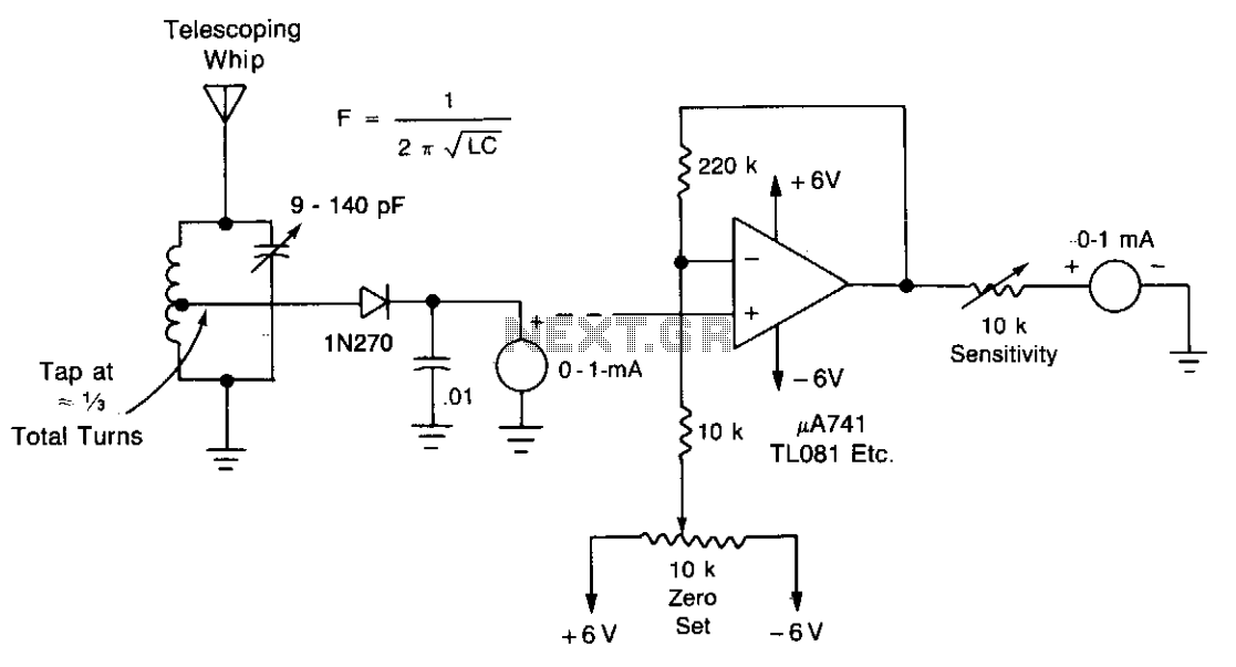
A field-strength meter with minimal components is presented here. For testing at greater distances, a DC amplifier can be added. It is recommended to use a single wire as the antenna. The field-strength meter is a simple yet effective device...
It is possible to synchronize the LEDs so that the speakers continue to play loudly while the LEDs are not always illuminated during music playback. The individual has a solid understanding of electrical concepts and is seeking a method...