
Ir Heat-Controlled Kitchen Fan
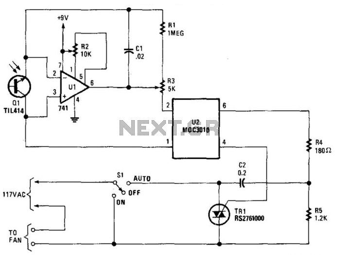
The circuit operates by utilizing an infrared (IR) sensor, designated as Q1, which detects the presence of heat sources. Upon detecting IR radiation, Q1 generates an output signal that activates the control circuit. The component U1 serves as a switching device, which, when energized by Q1, allows current to flow to the optocoupler U1. The optocoupler is critical for isolating the control side of the circuit from the high-voltage side, ensuring safety and preventing damage to sensitive components.
Once the optocoupler is activated, it sends a signal to TRIAC TR1. The TRIAC functions as a switch that can control the power delivered to the fan. When TR1 is triggered, it allows current to flow through the fan, activating it and providing cooling as needed. The choice of TRIAC is essential; a suitable component, such as a 200-V, 6-A TRIAC (C106B) or similar from Radio Shack, is recommended for this application to ensure it can handle the power requirements of the fan.
This circuit design is efficient for applications where automated cooling is required in response to heat detection, such as in HVAC systems or electronic device cooling solutions. The use of an optocoupler not only provides isolation but also enhances the reliability of the system by protecting the low-voltage control circuitry from high-voltage spikes that may occur when the TRIAC is activated. Overall, this combination of components creates a robust solution for controlling fan operation based on thermal input. Ql senses IR from heat sources, causes U1 to switch, activates optocopuler Ul, and triggers TR1. This contro ls a fan. The Triac is from Radio Shack, or else a 200-V, 6-A unit (C106B) can be used. 🔗 External reference
Related Circuits
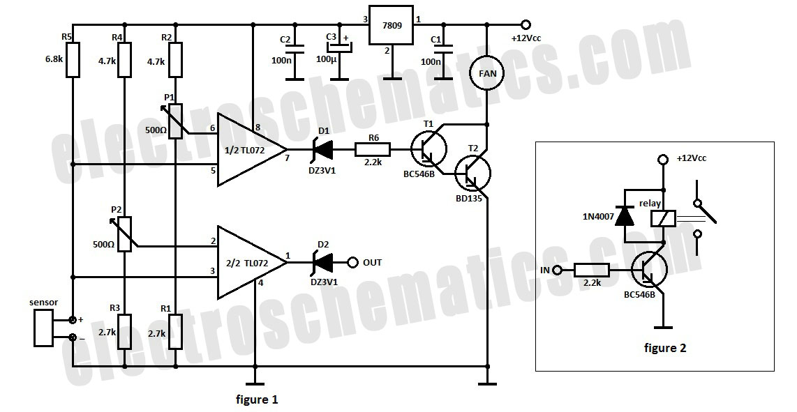
The automatic fan controller circuit depicted in the schematic features two comparators with distinct triggering points that can be adjusted independently. LM135 or... The automatic fan controller circuit is designed to regulate fan operation based on temperature variations. It employs...
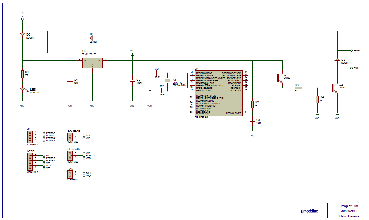
This project is based on a PIC18F25K20, with the purpose of controlling a fan with PWM (Pulse Width Modulation). It offers variable speed control, low acoustic noise, reliability, long lifetime, low power consumption, and protection features. The MCU gets...
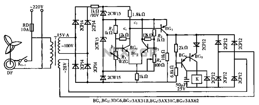
The circuit is a bistable circuit where each bistable unit is controlled by high and low output levels. When power is supplied to the circuit, current flows through components R13, CL, and VD to VD2 for full-wave rectification. The...
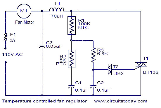
The function is designed to automatically control the speed of a fan based on the temperature. Components include a BT136 Triac, capacitor, resistor, relay, and fan motor. The circuit employs a temperature sensing mechanism to monitor ambient temperature levels. A...
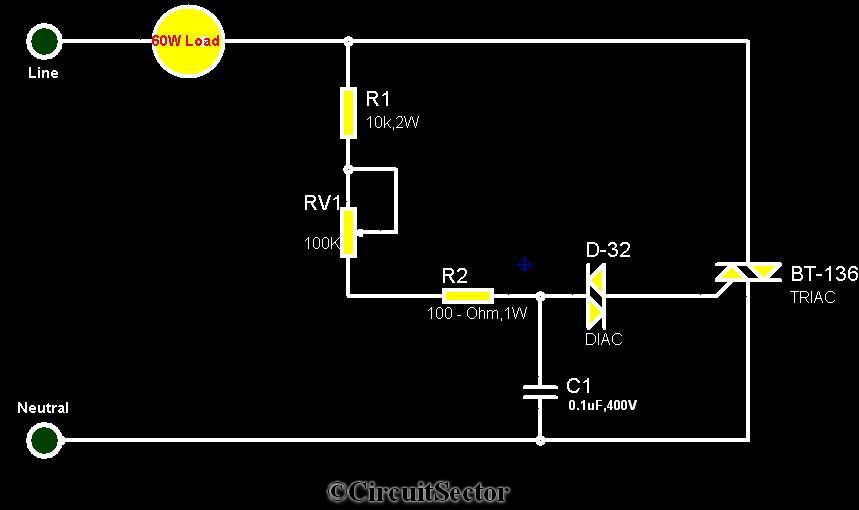
The circuit diagram presented is a triac-diac electronic fan regulator designed to reduce power consumption of electric fans, even at low speeds. Traditional resistor-inductor fan regulators tend to generate excess heat, wasting energy when the fan operates at lower...
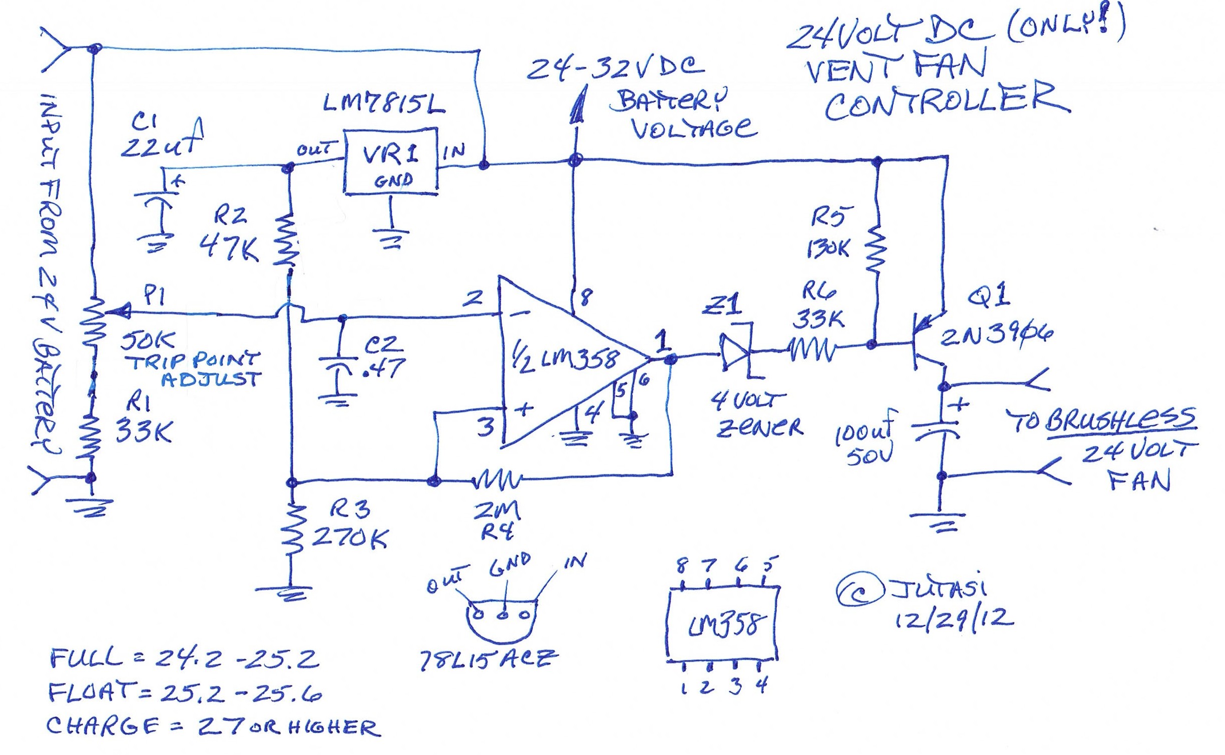
One of the backup systems utilizes a Magnum MS-PAE 4024 inverter, which lacks a built-in fan controller. Since batteries emit hydrogen during both normal and equalization charging, it is crucial to ventilate the batteries to the outside using a...