
ATmega8535 Line Follower Robot circuit diagram
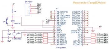
The line follower robot circuit is designed to autonomously navigate along a predetermined path, typically marked by a contrasting line on the ground. The core components of this circuit include eight proximity sensor modules, which are strategically positioned to detect the line's presence. Each sensor module consists of a photodiode that senses light reflection. When the robot is on the line, the sensors detect the reflected light, sending signals to the microcontroller, which processes the information to determine the robot's direction.
The L298 motor driver plays a crucial role in controlling the movement of the robot. It can drive two DC motors simultaneously, allowing for differential steering. This means that the speed and direction of each motor can be adjusted independently, enabling the robot to turn and navigate effectively. The L298 can handle a maximum output current of 2A per motor, making it suitable for small to medium-sized motors commonly used in robotic applications.
The design of the circuit also includes power management considerations, ensuring that the sensors and motors receive adequate voltage and current for optimal performance. The microcontroller, typically an Arduino or similar platform, interfaces with the sensor modules and motor driver, executing the logic required to keep the robot following the line. The overall architecture of the circuit is modular, allowing for easy modifications and upgrades as needed for advanced functionalities or improved performance.
In summary, the line follower robot circuit is a well-structured design that integrates sensor technology with motor control to achieve autonomous navigation, making it an excellent platform for educational purposes and robotics experimentation.This is the circuit diagram of Line Follower / Line Tracker robot. The circuit taken from the tutorial documentation. You may download the full tutorial at the end of this article. The line follower robot use 8 pieces of proximity sensor module. The sensor module use photodioda for detecting the reclection of light from the line/floor. The motor d river L298 able to control the motor with current output up to 2A for single DC motor. For double DC motors, there should be up to 1A for each output channel. This motor driver is very good for small and medium DC motor. L298 is great motor driver for small and medium size or robot such as line follower robot and fire fighter robot. 🔗 External reference
Related Circuits
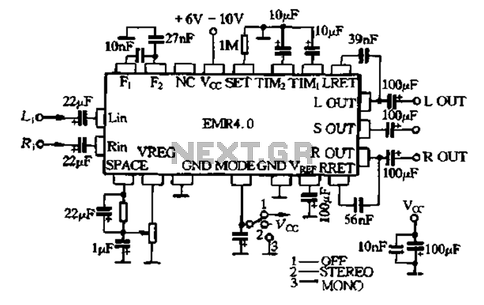
The EMR 4.0 operates with a single power supply ranging from 6V to 10V, with an optimal supply voltage of 9V. It requires effective power filtering to minimize noise, particularly when there is no signal input. The quiescent current...
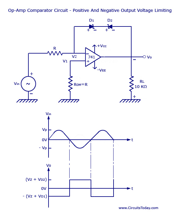
Voltage Limiter Circuit Using Op-amp - Circuit Diagram, Waveform, Positive and Negative Voltage Limiters. The voltage limiter circuit utilizing an operational amplifier (op-amp) serves to restrict the output voltage to predefined levels, effectively preventing it from exceeding or falling below...
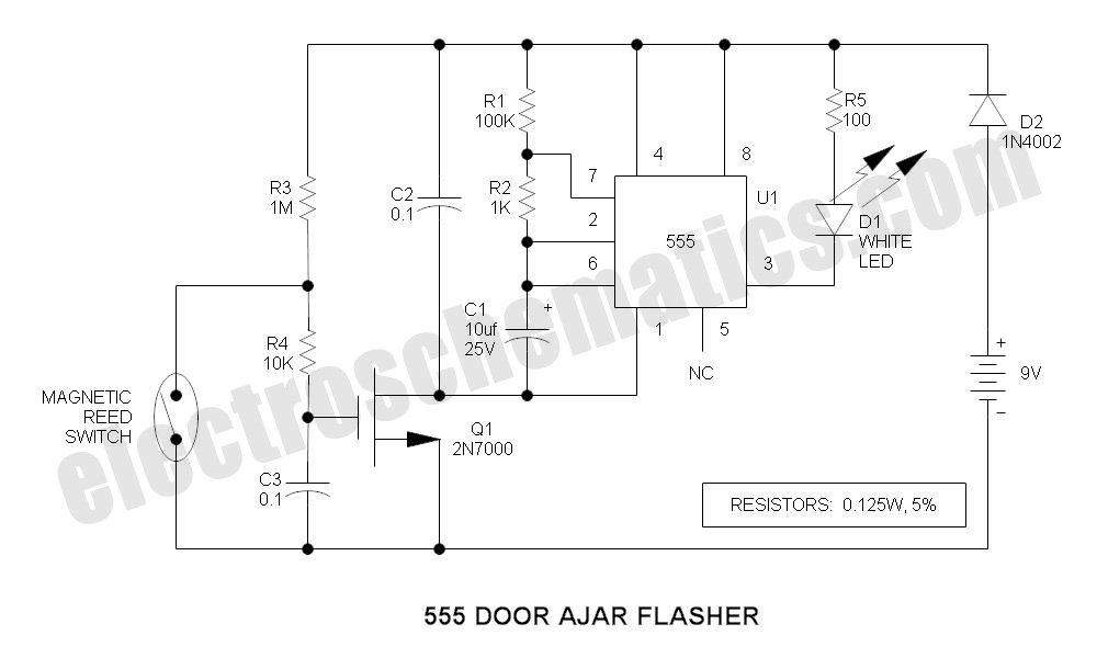
This is a compact LED flasher circuit designed using the 555 timer integrated circuit (IC), powered by two 1.5V batteries. The circuit can function as a flashing metronome, dark room timer, reminder, or for other similar applications. In the...
The automatic sprinkler controller circuit consists of a power supply circuit and a humidity measurement and control circuit, as illustrated in the accompanying figure. The power supply circuit includes a power transformer (T), rectifier diodes (VD1 to VD4), filter...
The circuit operates continuously, turning on and off. It utilizes the widely recognized NE555 timer IC, known for its versatility in various electronic applications. In this configuration, the IC is set up as an astable multivibrator. A 12-volt relay...
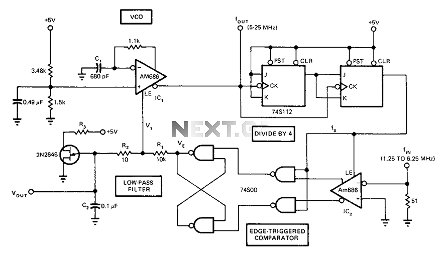
A circuit diagram of a phase-locked loop utilizes an AM686 latched comparator as a voltage-controlled oscillator, along with a TTL latch connected to generate edge-triggered comparators. The VCO and its comparison with the low-pass filter consisting of R1, R2,...
Warning: include(partials/cookie-banner.php): Failed to open stream: Permission denied in /var/www/html/nextgr/view-circuit.php on line 713
Warning: include(): Failed opening 'partials/cookie-banner.php' for inclusion (include_path='.:/usr/share/php') in /var/www/html/nextgr/view-circuit.php on line 713