
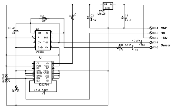
Proximity detector using NE567 IC. Switches LED when object comes near the sensor

The NE567 is a versatile phase-locked loop (PLL) device commonly used for applications such as proximity detection due to its ability to detect the presence of objects without physical contact. In this circuit, the NE567 is configured to operate as a proximity sensor by measuring the frequency of the incoming signal, which changes when an object comes within a certain range.
The circuit typically consists of the NE567 IC, a few passive components such as resistors and capacitors, and an LED. The input to the NE567 can be derived from a transmitter, like an ultrasonic or infrared emitter, which sends out a signal that reflects off nearby objects. When an object is detected, the reflected signal alters the phase of the input signal received by the NE567.
The LED is connected to the output of the NE567, which provides a high or low signal depending on the detection of an object. When the object approaches the sensor, the NE567 detects the change in frequency and switches the output to activate the LED. This provides a visual indication of proximity, making the system useful in various applications such as automatic lighting, security systems, or interactive devices.
The circuit can be further enhanced by adjusting the sensitivity through the use of variable resistors or by incorporating additional components for filtering or signal conditioning. This allows for greater flexibility in the design, enabling the proximity detector to be tailored for specific environments or detection ranges.Simple proximity detector circuit based on NE567 IC. Circuit switches an LED when the object comes near the sensor.. 🔗 External reference
Related Circuits
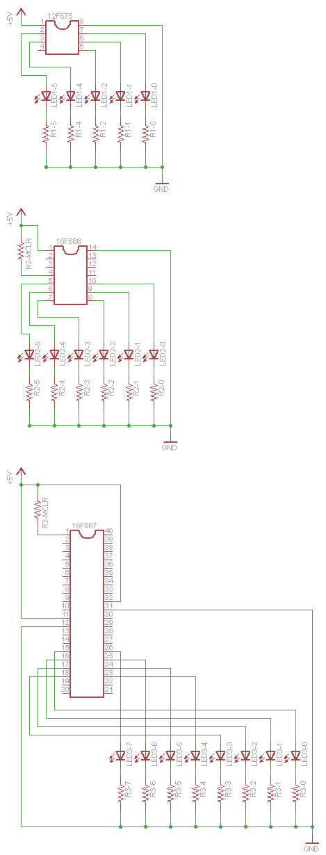
One of the drawbacks for some users is that Linux support for PIC microcontrollers is not widely known. The information is available, but the process of transitioning from writing C code to programming a chip has not been clearly...
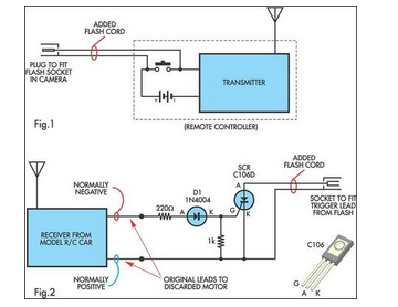
A radio-controlled electronic flash is an essential tool in any photographer's kit. Professionals frequently utilize them, such as wedding photographers. A radio-controlled electronic flash system typically consists of a transmitter and one or more receivers. The transmitter, often mounted on the...
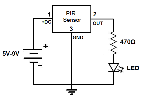
This circuit is designed to detect motion or movement, with its most common application being the detection of a person moving through an area covered by the motion detector. The primary electronic component utilized for this detection is the...
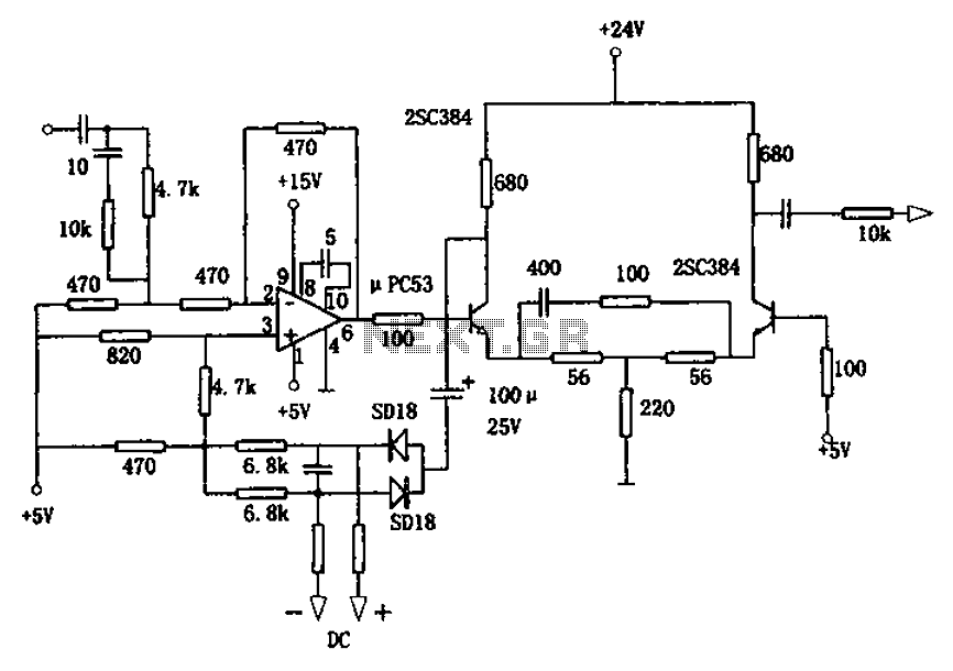
The circuit is designed for a broadband linear detection application with a bandwidth of 10 MHz. It serves as a millivoltmeter measuring instrument suitable for frequencies exceeding 10 MHz. The circuit features a linear detector utilizing operational amplifiers, specifically...
The following circuit illustrates the electrical circuit diagram for the 1976 Dodge Aspen. Features include the current register value of the IC DS2760. The electrical circuit diagram for the 1976 Dodge Aspen is a critical component for understanding the vehicle's...
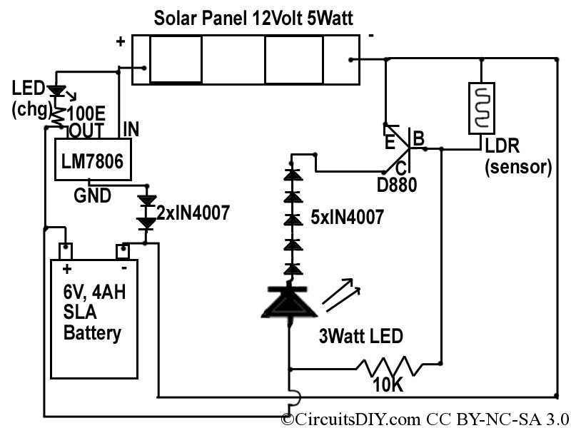
This document discusses a simple solar LED circuit. Solar panels range from 12 volts and 3 watts to larger sizes. To store energy, a 12-volt battery is required. The preferred choice is a sealed lead-acid (SLA) sealed maintenance-free (SMF)...