
LED Pumpkin Candles for Colorful Halloween Jack-O-Lanterns

The circuit design showcases a microcontroller-based LED pulsing system that enhances the functionality of discrete LEDs. By integrating a Microchip MCP1702 LDO voltage regulator, the circuit ensures stable operation at 5 volts, which is critical for the microcontroller's performance. The use of capacitors C1 and C2 is pivotal in maintaining a clean power supply, thereby enhancing the reliability of the circuit against noise and voltage fluctuations.
The Atmel ATTiny45 microcontroller serves as the core of the design, executing firmware that allows for dynamic control of LED brightness and pulsing rate. The ADC functionality enables real-time adjustments based on the trimpot's voltage, providing a user-friendly interface for modifying the LED effects. The transistor Q1 acts as a switch, efficiently controlling the current to the LEDs based on the microcontroller's PWM signals. This method of controlling brightness through rapid switching not only conserves power but also achieves a smooth dimming effect that is visually appealing.
Furthermore, the inclusion of a diode (D1) enhances the circuit's robustness by preventing potential damage from reverse polarity connections, which is a common risk in battery-operated circuits. The automated shutdown feature is an innovative addition, ensuring that the device conserves battery life, making it suitable for applications where long-term operation is desired without frequent battery replacements.
Overall, this circuit exemplifies the advantages of integrating microcontrollers into LED systems, providing flexibility, enhanced functionality, and improved user experience in electronic designs.Discrete blinking LEDs are convenient, but the blink rate and blink duration are not configurable. I tried goofing around with using transistors, resistors, and capacitors to alter the blinking LED. In the end, I had so many extra electronic components that I figured it would be easier to simply program the lighting effect with software. As soon a s a circuit includes a microcontroller (MCU), it cuts down on the number of hobbyists that are capable of implementing it. Nevertheless, I decided to include this more complex circuit in this article to demonstrate the possibilities.
A number of fancy electronics (computers, MP3 players, etc) now include a pulsing LED that fades in and out. For example, a pulsing LED may indicate that the device is sleeping (in a low power mode). The circuit has become much more complicated because the microcontroller can`t run on 9 volts. A Microchip MCP1702 LDO (low-dropout) voltage regulator (VR1) steps down the battery voltage to 5 volts for the microcontroller section.
Several capacitors (C1 and C2) steady the voltage supply to avoid electrical glitches and noise. A diode (D1) protects all of the electronics components against a reversed battery. This wasn`t necessary in previous circuits because the strands of LEDs wouldn`t be harmed by a reversed battery. But now, a microcontroller and other sophisticated semiconductor parts are installed, and they can be harmed by a flipped battery.
The Atmel ATTiny45 microcontroller has firmware (software inside a chip) that is written in C on a personal computer. The compiled software is then downloaded to the chip by an Atmel programmer. I use an Atmel STK500 board and the ImageCraft C compiler. In the circuit, the Atmel microcontroller reads the trimpot (R2) using the built-in Atmel ADC (analog-to-digital converter).
Depending on the voltage on the trimpot wiper, the microcontroller delays each increment or decrement of the LED brightness. Thus, by adjusting the trimpot, the rate of pulsing can be slowed down or sped up. All of the power going to the LEDs is controlled through a single bipolar NPN transistor (Q1). A resistor prevents too much electricity from entering the transistor base pin, which the microcontroller controls.
The LEDs can be turned on completely by the microcontroller outputting 5V on the OC1B pin. That turns on the transistor (Q1) which completes the path back to the battery for the LEDs. The LEDs can be turned off completely by the microcontroller outputting 0V on the OC1B pin. That turns off the transistor (Q1) which disconnects the path back to the battery for the LEDs. It`s as though the battery wire were disconnected from LEDs. To vary the brightness, the Atmel microcontroller switches the transistor on and off very rapidly. Because the microcontroller switches it so rapidly (four-thousand times a second), you don`t notice the blinking. The longer it is turned on versus turned off, the brighter the LEDs. This is called pulse-width modulation (PWM). The left half of the breadboard looks similar to earlier layouts. The right half of the breadboard is now crammed with other circuitry. The power from the battery now connects the upper right half of the breadboard, because the microcontroller needs to control the power going to the LEDs.
GND stands for ground . GND is the lowest voltage level for the IC chips in a circuit. In this case, GND is the negative terminal of the 9V battery. As an added bonus feature, the Atmel AVR microcontroller timer automatically shuts off the LEDs after a certain period of time (presently 5 hours). So, you don`t have to worry about draining the battery by accidentally leaving it on all night. Of course, the battery won`t be fresh when the LED candle turns off. But, the point is that the shutoff mode uses very little power. This may be particularly useful to avoid deeply draining a rechargeable battery. If you`re interested, I am willing to 🔗 External reference
Related Circuits
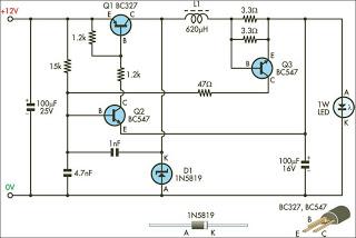
This circuit is designed to drive 1W LEDs that are commonly available. It addresses their non-linear voltage-to-current relationship and variations in forward voltage. The circuit utilizes a constant current driver configuration to ensure that the LEDs operate efficiently while maintaining...
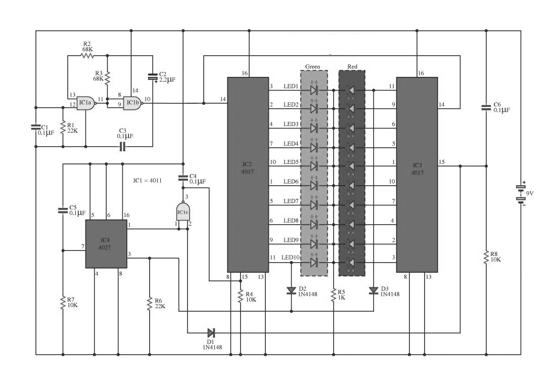
This circuit operates on alternating two colors using a 2-color LED with a built-in 3-pin configuration. It alternates the glow of each LED until the base, switching between two colors. The circuit comprises a NAND gate IC, two 10-counter...
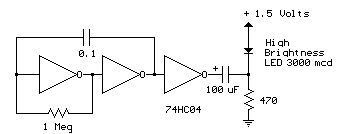
Several 1.5 V LED flasher circuits can be found online, and four of them are presented here. The flasher circuits operate on a single 1.5 V power supply. The design of a 1.5 V LED flasher circuit typically involves a...

Here is another project that creates a scrolling LED display. This display consists of 64 LEDs arranged in a matrix configuration. The anodes are driven through a driver circuit. The scrolling LED display project utilizes a matrix of 64 LEDs,...
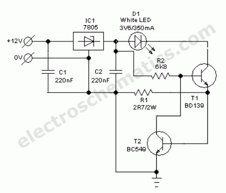
Without a dedicated buck converter or white LED driver IC, it is possible to safely drive multiple standard high-efficiency white LED modules using available battery power. To design a circuit capable of driving high-efficiency white LED modules without a dedicated...

A Direct-Coupled 6V6 Tube Amplifier with Cathode Follower by Raymond H. Bates from Radio & Television News magazine, November 1949. The Direct-Coupled 6V6 Tube Amplifier is designed to utilize a 6V6 vacuum tube, which is known for its warm sound...