
1W LED Driver

The circuit utilizes a constant current driver configuration to ensure that the LEDs operate efficiently while maintaining their rated performance. The primary components of this circuit include a power supply, a current sensing resistor, and a feedback mechanism to regulate the output current.
The power supply provides the necessary voltage to the circuit, which is typically higher than the forward voltage of the LED to ensure proper operation. The current sensing resistor is placed in series with the LED, allowing the circuit to monitor the current flowing through the LED. By measuring the voltage drop across this resistor, the circuit can determine the actual current flowing through the LED.
A feedback loop is implemented using an operational amplifier or a dedicated LED driver IC. This feedback mechanism adjusts the output voltage to maintain a constant current, compensating for variations in the LED's forward voltage due to temperature changes or manufacturing tolerances.
To enhance thermal management, appropriate heat sinking should be considered, as 1W LEDs can generate significant heat during operation. Additionally, the circuit may include protective features such as overcurrent protection, thermal shutdown, and reverse polarity protection to ensure the longevity and reliability of the LEDs.
Overall, this circuit design effectively addresses the unique characteristics of 1W LEDs, providing a reliable and efficient solution for various lighting applications.This circuit is designed to drive the 1W LEDs that are now commonly available. Their non-linear voltage to current relationship and variation in forward v.. 🔗 External reference
Related Circuits
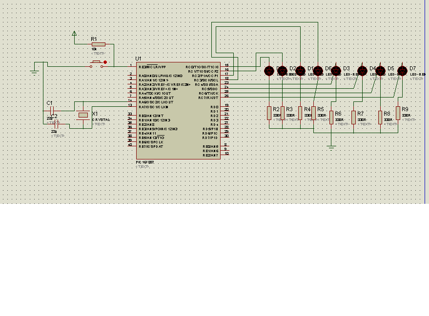
The code in mikroC PRO for the PIC16F887 microcontroller is designed to operate with an 8.000 MHz clock frequency on a Microchip 44-pin demo board. The routines have been developed using HITECH C, but the focus is on utilizing...
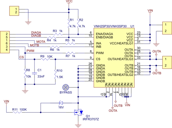
Need more current? If you have a larger motor ready for use, the Pololu High Current Motor Driver Board 14A 6V-16V is the ideal solution. Connect three digital lines to your microcontroller (five if error condition feedback is desired),...

The YouTube video below demonstrates the quick and easy setup of the system at the launch site. The provided description indicates a focus on the efficiency of system installation at a launch site, as showcased in a YouTube video. In...
When the input voltage is 0 the LED glows. The LED stops glowing when the voltage rises to the level determined by R2. Reverse + and - pins to reverse operating mode. To set voltage at which LED goes...

The following circuit illustrates a two-transistor DC motor driver circuit diagram. This circuit utilizes the TIP32 transistor. Features: operates in... The two-transistor DC motor driver circuit is designed to control the operation of a DC motor using two NPN transistors,...

The amplifier achieves a total power gain of approximately 25 dB, utilizing a construction technique that incorporates low-cost components throughout. The MRF476 is rated as a 3-watt device, while the MRF475 delivers an output power of 12 watts. Both...