
A Direct-Coupled Amplifier with Cathode Follower by Raymond H. Bates
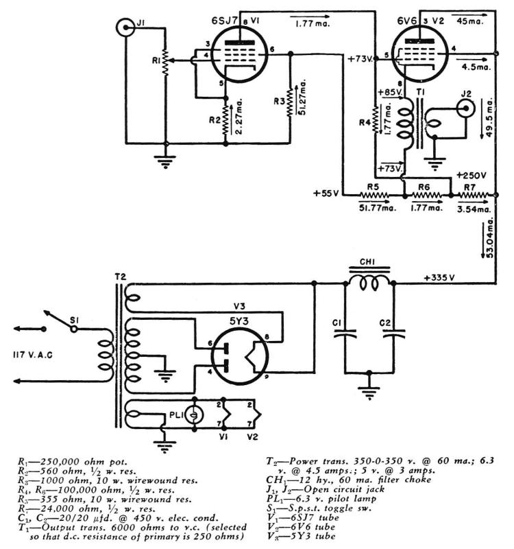
The Direct-Coupled 6V6 Tube Amplifier is designed to utilize a 6V6 vacuum tube, which is known for its warm sound and high fidelity in audio amplification. This amplifier incorporates a cathode follower stage, which serves to buffer the output of the amplifier while maintaining a high input impedance and low output impedance. The direct coupling between stages eliminates the need for coupling capacitors, allowing for a more seamless signal transfer and improved frequency response.
The circuit typically consists of a power supply providing the necessary high voltage for the 6V6 tube, along with a filament supply for heating the tube. The input stage may include a preamplifier section, which is often based on another tube, such as a 12AX7, to provide initial signal amplification. The output stage, featuring the 6V6, is responsible for driving the speakers, delivering rich audio output.
The cathode follower configuration is implemented to drive the load efficiently, ensuring that the output signal retains its integrity without significant distortion. This configuration also allows for better voltage swing capabilities, which is crucial for audio applications.
Overall, the Direct-Coupled 6V6 Tube Amplifier with Cathode Follower is a classic design that exemplifies the advantages of tube technology in audio amplification, offering both aesthetic appeal and high-quality sound reproduction. Its design principles remain relevant in modern audio applications, reflecting the enduring legacy of vacuum tube amplifiers.A Direct-Coupled 6V6 Tube Amplifier with Cathode Follower by Raymond H. Bates from Radio & Television News magazine November 1949 🔗 External reference
Related Circuits
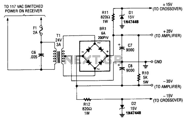
This power supply is designed to power a 100-W low-frequency amplifier and is capable of supporting various mono or stereo amplifiers within the medium power range, specifically those that require 30 to 35 V. The power supply circuit is engineered...
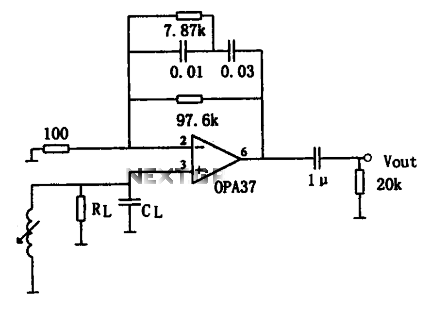
The OPA37 serves as a low-noise preamplifier. The input signal is connected to the inverting input of the OPA37 (pin 3), while the circuit components RL and CL represent the load impedance for electromagnetic pickups. The resistance and capacitance...
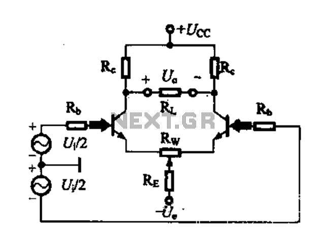
A differential amplifier circuit can be configured in four different connection methods, allowing for a comparison of characteristics such as gain and common-mode rejection ratio (CMRR). This analysis focuses on symmetrical circuits and their performance in handling common-mode signals. The...
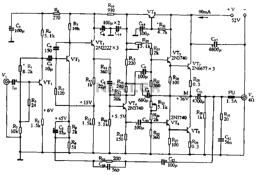
The circuit depicted in the figure is a highly technical OTL (Output Transformer-Less) amplifier circuit. It features a frequency response range of 10 Hz to 100 kHz and exhibits a total harmonic distortion of less than 0.1%, which is...
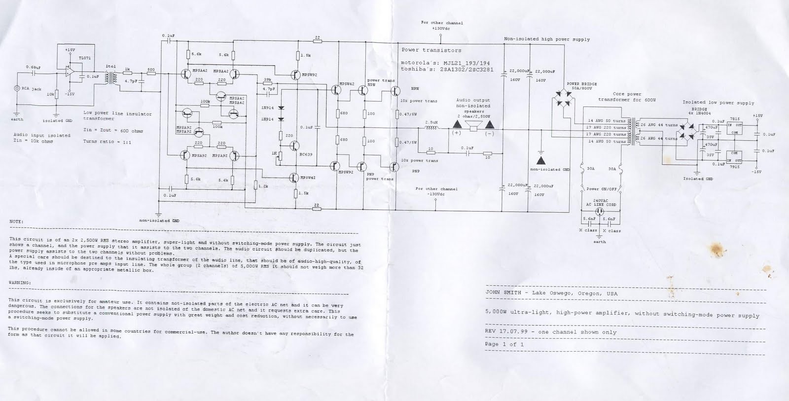
This device is a 2x2, 500W RMS stereo amplifier, designed to be super-lightweight and equipped with a switching-mode power supply. The device features a single channel display and specifies the power output it provides to both channels. The audio...
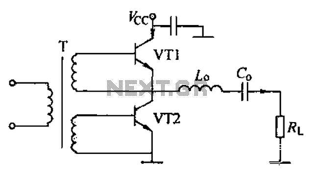
A complementary voltage switching Class D amplifier circuit is presented. Transistors VT1 and VT2 are 3DA12 types, while another transistor, VT3, is of the 3DK41C type. The collector is connected to a constant DC voltage of 12V. The input...
Warning: include(partials/cookie-banner.php): Failed to open stream: Permission denied in /var/www/html/nextgr/view-circuit.php on line 713
Warning: include(): Failed opening 'partials/cookie-banner.php' for inclusion (include_path='.:/usr/share/php') in /var/www/html/nextgr/view-circuit.php on line 713