
led rf signal meter
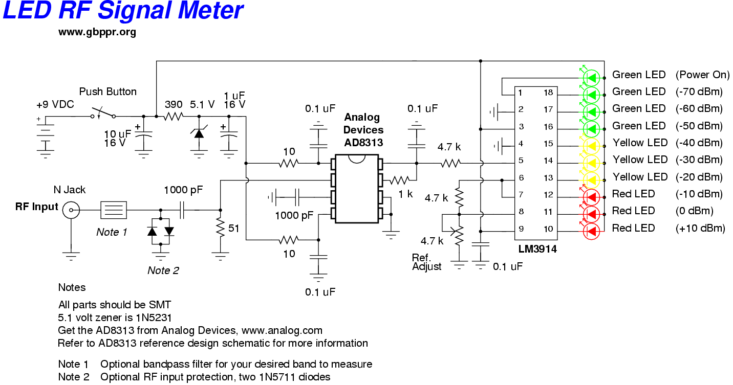
The RF Wave Absorption meter utilizes a simple yet effective design for detecting radio frequency signals across a specified range. The core component of the circuit is the germanium OA91 diode, which serves as a detector for incoming RF signals. The diode's characteristics allow it to rectify the RF signal into a direct current (DC) level, which can then be processed by the 10 LED driver integrated circuit (IC).
The gain adjustment potentiometer, rated at 22 MegOhms, provides the user with the ability to fine-tune the sensitivity of the circuit. By adjusting this potentiometer, the user can optimize the meter's response to varying signal strengths, allowing for effective detection over the entire range of 10 cm to 10 m.
The LED indicators, numbered 1 through 10, provide a visual representation of the detected signal strength. Each LED corresponds to a specific range of signal amplitudes, allowing the user to easily assess the relative strength of the RF signals being detected. This feature is particularly useful for applications such as tuning low-power transmitters, where precise adjustments are necessary to achieve optimal performance.
For applications requiring specific frequency detection, the circuit allows for the integration of a parallel tuned circuit in place of the OA91 diode connected to the negative terminal. This modification enables the user to filter and isolate particular frequency bands, enhancing the meter's functionality. The tuning components—inductors (L) and capacitors (C)—are specified for various frequencies, allowing for customization based on the user's needs. The use of 22 SWG wire for winding the coils on a 10 mm air former ensures adequate inductance while maintaining a compact form factor.
In summary, the RF Wave Absorption meter is a versatile tool for RF signal detection, offering adjustable sensitivity and frequency tuning capabilities to meet a variety of electronic applications.This RF Wave Absorbion meter will detect signals between 10cms and 10m away all acording to the setting of the 22MegOhm gain adjustment potentialometer and the power of the transmitter. The RF signal is detected across the germamium OA91 doides and rectified to a d. c. level driving a 10LED driver IC. The LED`s are marked 1 to 10 indicating the stren gth of the detected RF signal. This circuit is ideal for tuning up low power transmitters or locating hidden transmitters. If a specific frequency band is required, replace the OA91 diode that goes to negative with a parrallel tuned circuit as indicated. For 27MHz L=10Turns and C=39PF, for 50MHz L=7turns and C=27pF, for 80MHz L=5turns and C=12pF, for 110MHz L=4turns and C=10pF, for 150MHz L=3turns and C=8.
2pF and for 180MHz L=2Turns and C=2. 2pF. All coils are 22SWG wound on a 10mm air former. 🔗 External reference
Related Circuits
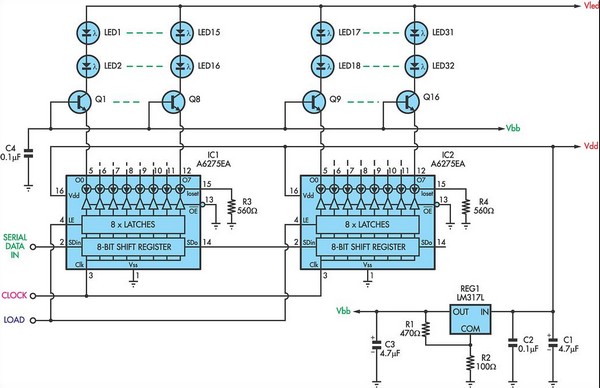
For applications requiring a large number of LEDs, traditional methods can become inefficient, prompting the need to minimize the voltage drop across the resistor. This approach can lead to inadequate current control. Integrated circuits (ICs) like the MM5450 and...
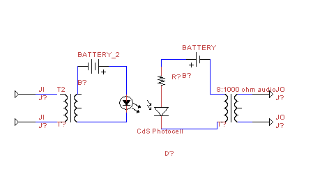
This circuit transmits audio information using light waves. It employs amplitude modulation (AM) to vary the intensity of an LED, which is detected by a cadmium sulfide photocell that changes its resistance based on light intensity. The circuit includes...
.gif)
This circuit utilizes a single integrated circuit (IC) along with a minimal number of external components to display audio levels through ten LEDs. The input voltage range is from 12V to 20V, with a recommendation for 12V. The LM3915...
This is an electric thermometer circuit composed of the LM134. In the circuit, the voltage or current output by the LM134 is proportional to the thermodynamic temperature, which can be read on a 100 µA meter. The test temperature...
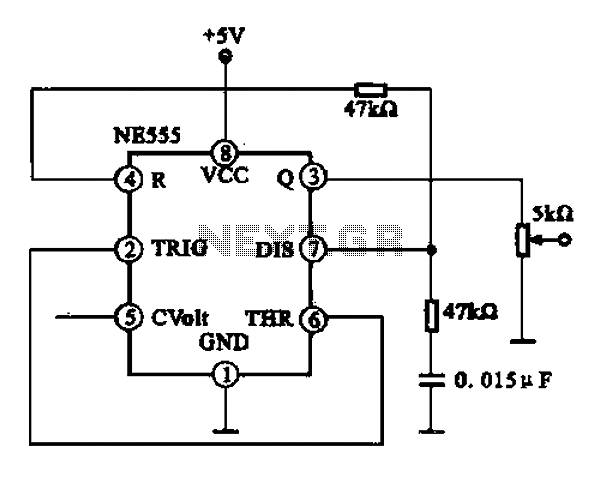
A 1 kHz square wave signal generator is created using a time base circuit with an NE555 timer, combined with a time constant circuit consisting of a 47 kΩ resistor and a 0.15 µF capacitor. The circuit utilizes the...
This circuit indicates the power level delivered to a loudspeaker. A dual-color LED displays green at approximately 1 watt, orange at 1.5 watts, and bright red at levels exceeding 3 watts. The circuit is connected in parallel with the...