LED Torch Uses Blocking Oscillator

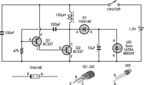
This simple LED torch is driven by a 2-transistor blocking oscillator that steps up the voltage from a 1.5V cell. It relies on the inherent current limiting of the 150 µH choke to protect the white LED from overdrive. With a 9V zener diode in place of the white LED, it could also provide a 9V supply, provided the current drain is modest.
The LED torch circuit operates using a 2-transistor blocking oscillator configuration, which is an efficient method for voltage amplification. The primary components include two transistors, a choke (inductor), and a white LED. The transistors are configured to alternately switch on and off, creating a pulsed output that energizes the choke. As the choke stores energy in its magnetic field, it releases this energy back into the circuit, resulting in a higher voltage output suitable for powering the LED.
The choke, rated at 150 µH, plays a critical role in current limiting. It prevents excessive current from flowing through the LED, which could lead to thermal runaway and damage. The inherent properties of the choke ensure that the current remains within safe limits while still allowing sufficient brightness from the LED.
In an alternative configuration, replacing the white LED with a 9V zener diode enables the circuit to function as a voltage regulator. The zener diode can maintain a stable 9V output, making it suitable for powering other low-power devices, provided that the current draw remains within the circuit's capabilities. This versatility enhances the utility of the circuit, enabling it to serve dual purposes as both an LED torch and a voltage supply.
Overall, the design effectively combines simplicity with functionality, making it an ideal choice for DIY electronics enthusiasts and applications requiring efficient power conversion.This simple LED torch is driven by a 2-transistor blocking oscillator which steps up the voltage from a 1. 5V cell. It relies on the inherent current limiting of the 150 µH choke to protect the white LED from over-drive.
With a 9V zener diode in place of the white LED, it could also provide a 9V supply provided the current drain is modest. 🔗 External reference


