
Controlling a LED using a switch

The circuit design consists of an Arduino microcontroller, a switch, an LED, and two resistors (10kΩ and 470Ω). The switch is connected to one side of the Arduino digital pin, while the other side is connected to ground through the 10kΩ resistor. This configuration ensures that when the switch is open (not pressed), the digital pin is pulled low to ground, preventing it from floating. The 10kΩ resistor serves to limit the current to the ground, thus protecting the microcontroller from excessive current draw.
When the switch is closed (pressed), the digital pin is connected to the positive voltage supply (5V), allowing current to flow through the 470Ω resistor and the LED. The LED will illuminate as long as the switch is pressed, and the 470Ω resistor serves to limit the current through the LED to a safe level, preventing damage.
The software component requires initializing the digital pins in the Arduino environment. A loop continuously checks the state of the switch. If the switch is detected as pressed, the LED will be activated; if not, the LED will remain off. The use of an infinite loop allows for real-time monitoring of the switch state, ensuring immediate response to user input.
This circuit is a fundamental example of interfacing digital inputs and outputs with an Arduino, showcasing basic principles of electrical engineering, such as current limiting, voltage levels, and digital logic. Proper implementation guarantees efficient operation while safeguarding the components involved.To create the circuit you will need to connect a switch as an input and an LED as an output to the Arduino. This means that you will need a switch, an LED, a 10k © resistor, a 470 © resistor, a blue or yellow jumper wire, and a red jumper wire.
The Arduino pin is connected to the circuit between the resistor and the switch. This is because the digital pin is configured such that it needs a small amount of power to change states. This is useful since we don`t want to draw too much power through the Arduino. However, this also means that if the pin is not connected to a known level in the circuit, it could have any value. This is called floating, since the value of the pin is neither high nor low. To solve this problem we use the resistor to connect the pin to ground. We use a resistor and not just a wire so that we can limit how much current is flowing through the connection.
Since we want to minimize the power draw we will use a large resistor, in this case 10k ©. When the switch is not pressed the pin is only connected to ground through the resistor. Since the pin will have what ever voltage value is applied to it, the resistor can be considered as a wire when the switch is not pressed. However, once the switch is pressed, the pin is directly connected to 5V and the resistor limits the current flowing to just 0.
5 mA, and thus prevents a short circuit. Now that we have everything connected, we need to tell ROBOTC how to configure the pins before we can program. We need to tell ROBOTC that we are using the Parallax BOE Shield, and that we have the LED connected to pin 5.
We also need to tell ROBOTC that pin 2 is a Digital High Impedance (the led switch with the resistor connected to ground) and name it "ledSwitch". We want the Arduino to turn the LED on when the button is pressed and turn it off when it is not pressed.
To do this we will need an infinite while loop and a way to determine the state of the switch. There are a lot of different ways to do this, but for now we will just use a second while loop that only runs when the button is pressed: The "=" means to check if the values to either side are equal. If the values are equal, then it will return true, otherwise it will return false. This is different than the single equals sign "=", which is used when assigning values. So by placing that code inside the second while loop`s condition, we can make that loop only run when the switch is pressed.
🔗 External reference
Related Circuits

Another application of the frequency-to-voltage converter (FVC) is the tone/frequency decoder. This circuit is designed to identify the frequency band of an oscillating signal. It is utilized in various applications, such as determining the frequency band in signals and...

The circuit described utilizes a quad voltage comparator (LM339) to function as a simple bar graph meter that indicates the charge status of a 12-volt lead-acid battery. A 5-volt reference voltage is employed for this purpose. The circuit leverages the...

This ultra-bright white LED lamp operates on 230V AC with minimal power consumption. It is suitable for illuminating VU meters, SWR meters, and similar applications. The cost of ultra-bright LEDs available in the market ranges from Rs 8 to...

An ultralow dropout current source maintains accurate LED current at very low ILED voltages. Automatic mode switching optimizes efficiency by monitoring the voltage across the LED current source and switching modes only when ILED dropout is detected. The LTC3216...
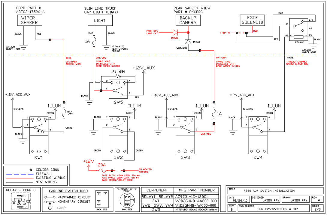
A +12V switched wire was routed back to the camera wiring and connected at the same point as the reverse lights. This configuration allows either the reverse lights or the switch to activate the camera. The critical component in...

This design outlines a sensor circuit that utilizes an LED as a light sensor. The operational control and amplification of the output are managed by a 1458 integrated circuit (IC), which functions as an operational amplifier (op-amp). The circuit...
Warning: include(partials/cookie-banner.php): Failed to open stream: Permission denied in /var/www/html/nextgr/view-circuit.php on line 713
Warning: include(): Failed opening 'partials/cookie-banner.php' for inclusion (include_path='.:/usr/share/php') in /var/www/html/nextgr/view-circuit.php on line 713