
MAX8596Z drive circuit diagram of eight white LED

Driving a series of white LEDs requires careful consideration of the electrical parameters to ensure uniform brightness and operational efficiency. Each LED in the series must have the same current flowing through it, which is critical for achieving consistent luminance across the entire array. The forward voltage drop of each LED must be taken into account when calculating the total driving voltage, as the sum of these drops will dictate the minimum output voltage required from the power supply.
To facilitate the necessary voltage boost, a tandem switch inductive boost converter is employed. This type of converter is designed to step up the input voltage to a higher output voltage, which is essential when dealing with multiple LEDs in series. The efficiency of the converter is paramount, especially in high-pressure applications, as it minimizes energy loss and heat generation.
When selecting an inductive boost converter, it is vital to examine the rated output voltage of the LX pin, as this component plays a crucial role in determining the converter's capability to drive a specific number of LEDs. The converter's specifications should align with the voltage requirements of the LED string to ensure safe and reliable operation.
Additionally, the design must consider a safety margin between the maximum rated voltage of the LEDs and the LX pin voltage. This margin is critical to prevent overvoltage conditions that could damage the LEDs. As such, it is advisable to reference the provided table of inductive boost converters to identify suitable devices that can meet the voltage and current requirements of the LED series while ensuring adequate protection against voltage spikes.
In conclusion, the successful implementation of a series white LED driver circuit hinges on the careful selection of components, particularly the tandem switch inductive boost converter, to achieve the desired performance and reliability in LED illumination applications.Driving series white LED, flowing through the same song in each white LED current, it is possible to obtain a uniform brightness. The disadvantage of the tandem drive is the dr ive voltage for the white LED forward voltage drop and the sum of the drive output voltage amplitude should meet after the series LED drive voltage required. This configuration requires tandem switch inductive boost converter in order to obtain high efficiency at high pressure.
When choosing this type of converter must be considered LX pin rated output voltage. The table below shows several inductive boost switching converter Lx pin rated voltage and can drive series white LED number. The need to retain the maximum voltage between the maximum rated voltage of white LED in series with the Lx pin certain safety margin to allow for overvoltage shutdown.
Select the appropriate table series LED device drivers required
Related Circuits
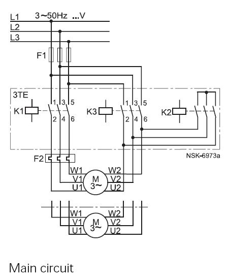
This method reduces starting current and starting torque. The device typically consists of three contactors, an overload relay, and a timer for setting the duration in the star position (starting position). The motor must be delta connected during normal...
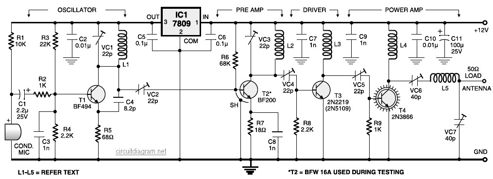
A four-stage FM transmitter circuit diagram utilizes four radio frequency stages: a VHF oscillator designed around the BF494 transistor (T1), a preamplifier based on the BF200 transistor (T2), a driver built with the 2N2219 transistor (T3), and a power...
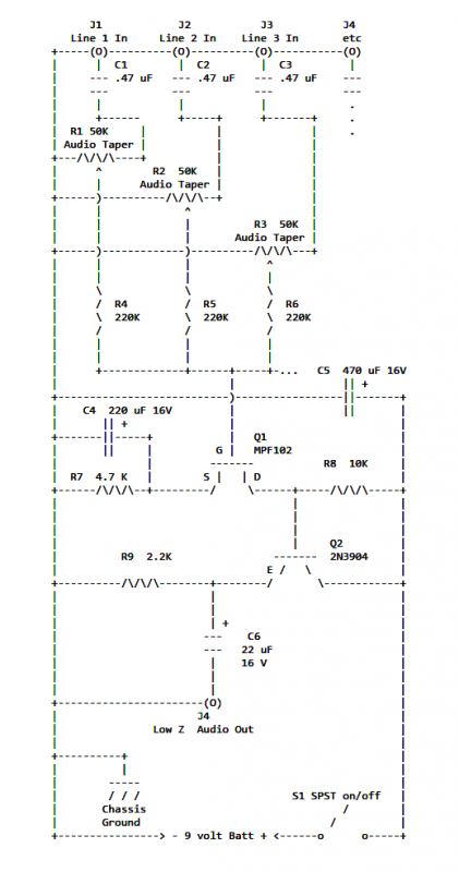
If two of these circuits are made in the same enclosure for stereo, then there can be a single power supply to run both of them. There should be a resistor in series with the incoming 9V+ lead so...
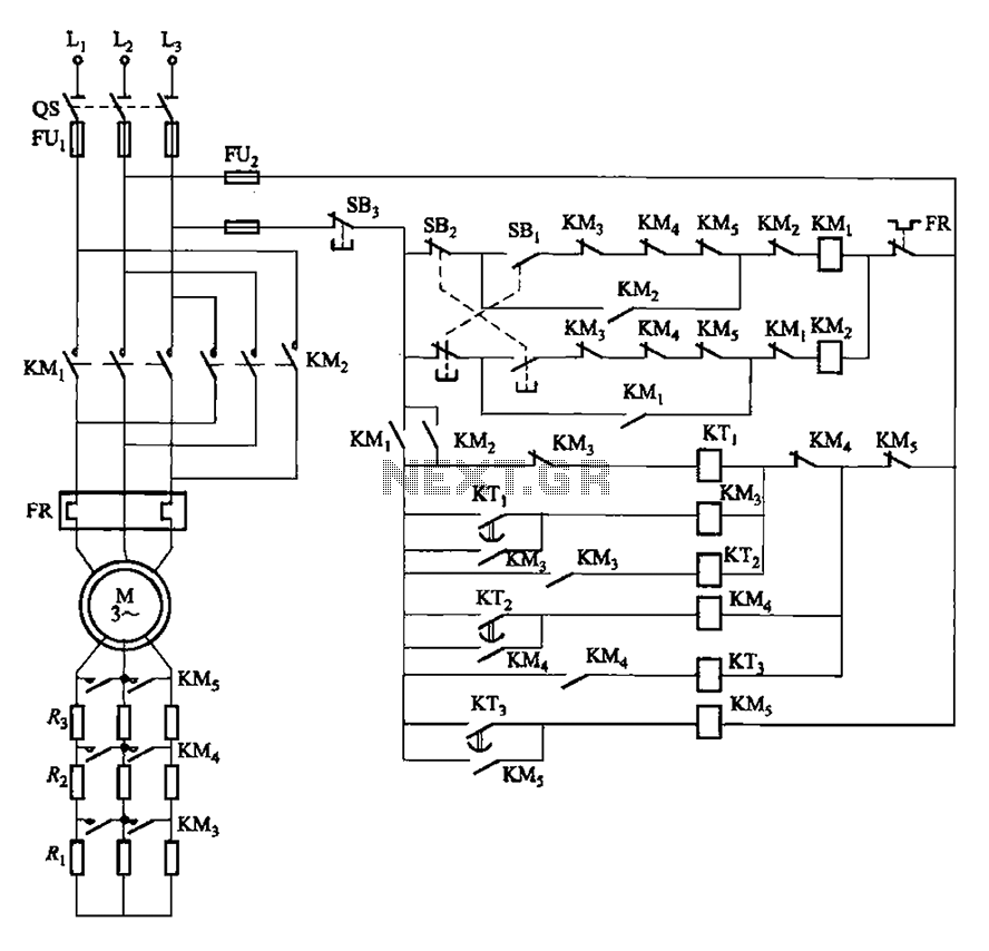
The circuit depicted in Figure 3-162 includes several components: SBi serves as the forward start button, SBz functions as the reverse start button, and SB3 is designated as the stop button. The resistance levels for the start switches are...
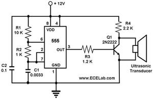
The ultrasonic cleaning machine functions as a humidifier and operates on a simple circuit primarily consisting of an ultrasonic oscillator. It generates ultrasonic frequency signals, typically within the range of 20-40 kHz, using a transistor. These signals are transmitted...
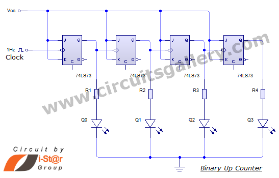
This document discusses an Asynchronous 4-Bit Binary Up Counter, a circuit constructed from several J-K flip-flops connected in a cascade configuration to produce a four-bit counting sequence. An up counter is a digital counting circuit that increments its count...
Warning: include(partials/cookie-banner.php): Failed to open stream: Permission denied in /var/www/html/nextgr/view-circuit.php on line 713
Warning: include(): Failed opening 'partials/cookie-banner.php' for inclusion (include_path='.:/usr/share/php') in /var/www/html/nextgr/view-circuit.php on line 713