
Lego Rotation Sensor Internals
The Lego rotation sensor employs a sophisticated design that enables precise measurement of rotational movement. The sensor's operation hinges on a dual-phase communication system with the RCX, allowing it to switch between power and read modes efficiently. The reliance on capacitors to store energy during the power phase is critical, as it ensures that the sensor can function independently during the read phase. The four-level code used for communication is essential for differentiating the sensor's output states, which correspond to the position of the axle.
The transition issues observed during low-speed rotations highlight the importance of timing in the sensor's operation. The jitter in the read phase duration can lead to inconsistencies in the output, particularly during critical transitions. This behavior necessitates careful consideration during programming, especially when using alternative software that implements double sampling to reduce the likelihood of misreads.
The internal architecture of the sensor, featuring diodes for power rectification and capacitors for filtering, underscores the sensor's design complexity. The use of opto-forks for detecting rotational movement through infrared interruption is a clever application of optical sensing technology, allowing for high-resolution measurements. The propeller-shaped blades effectively increase the number of detectable steps per rotation, enhancing the sensor's performance.
Overall, the Lego rotation sensor exemplifies the integration of electronic components and software algorithms to achieve precise rotational measurements, though it also illustrates the challenges associated with low-speed operation and the need for robust error mitigation strategies.Lego rotation sensor is a nice little device that enables RCX to measure rotation of an axle with good resolution: 16 steps per turn. Unfortunately it is plagued with a problem: at low rotation speed value read seems to jump randomly from 1 or two units.
So I decided to have a fairly indiscrete look at it. here is what I discovered. Active sensors (rotation sensor, light sensor) communicate with RCX through a two phases scheme: during 2. 9ms, RCX powers sensor (+8V), then during about 100 µs RCX reads analog value returned by sensor. During read phase, no power is provided to sensor, and this one has to live on its own reserve. This is done by storing energy in a capacitor during power phase. Here is a zoom on read phas of a rotation sensor. Numerous traces are accumulated over some time while rotating axle of sensor. You can see that sensor communicates with RCX through a 4 levels code. The voltages I measured for this levels are: These values seem a bit low when compared to Michael Gasperi`s (see his rotation sensor page ), perhaps my batteries were exhausted. You can also see that there is some jitter in read phase duration (between 90 µs and 125 µs) As the axle is rotated clockwise, output cycles througs steps 1 > 2 > 3 > 4 > 1, and through steps 1 > 4 > 3 > 2 > 1 when rotated ccw.
This enables RCX to determinate rotation direction. As pointed out by here by JG rgen Stuber, we have here the first problem of rotation sensor: during transition between step 3 and 4, output crosses voltage of level 2, and between step 1 and 2, output crosses voltage of level 4. Since this transition takes some time, there is a probability that it happens just when RCX samples value.
I tried to determine sampling time, it seems to take place about 60 µs after beginning of read phase. Here is such a transitionbetween step 3 and step 4. We can see that transition time across 3. 3V (step 2) can be evaluated to 1 µs. Sampling is done every 3 ms, probability of misread can be evaluated to about 1/3000 at most. Some alternative RCX programming languages (legOS and leJOS) perform two consecutive readings and almost eliminate this problem at the cost of halving maximum rotation speed.
To obtain this trace, I simply rotated sensor by hand very slowly till I reached transition between steps. And instead of having a sudden jump between two values, I got a stable oscilloscope trace (hand shaking apart) showing a transition each 3ms!
And moving VERY little my hand I could modify the position of this transition, and especially place it just at sampling point - and counter began to jump between values. It seems that very close to transition position, there is synchronisation with power/read cycle, and this increases the previous problem: there is a lot of transitions instead of only one - and when rotating very slowly this transition is doomed to occur at sampling point and cause misread.
Note that even double sampling as performed by legOS and leJOS has no guarantee to give correct answer: if rotation is very slow two successive reads will happen during transition. To go further, I needed to look inside the sensor. Prying it open proved painful. I first cut the blue tabs below the baseplate, but sensor didn`t open. It seems that some tabs are glued or heat soldered, so I had to resort to brute force methods and cut everywhere between dark grey and blue parts.
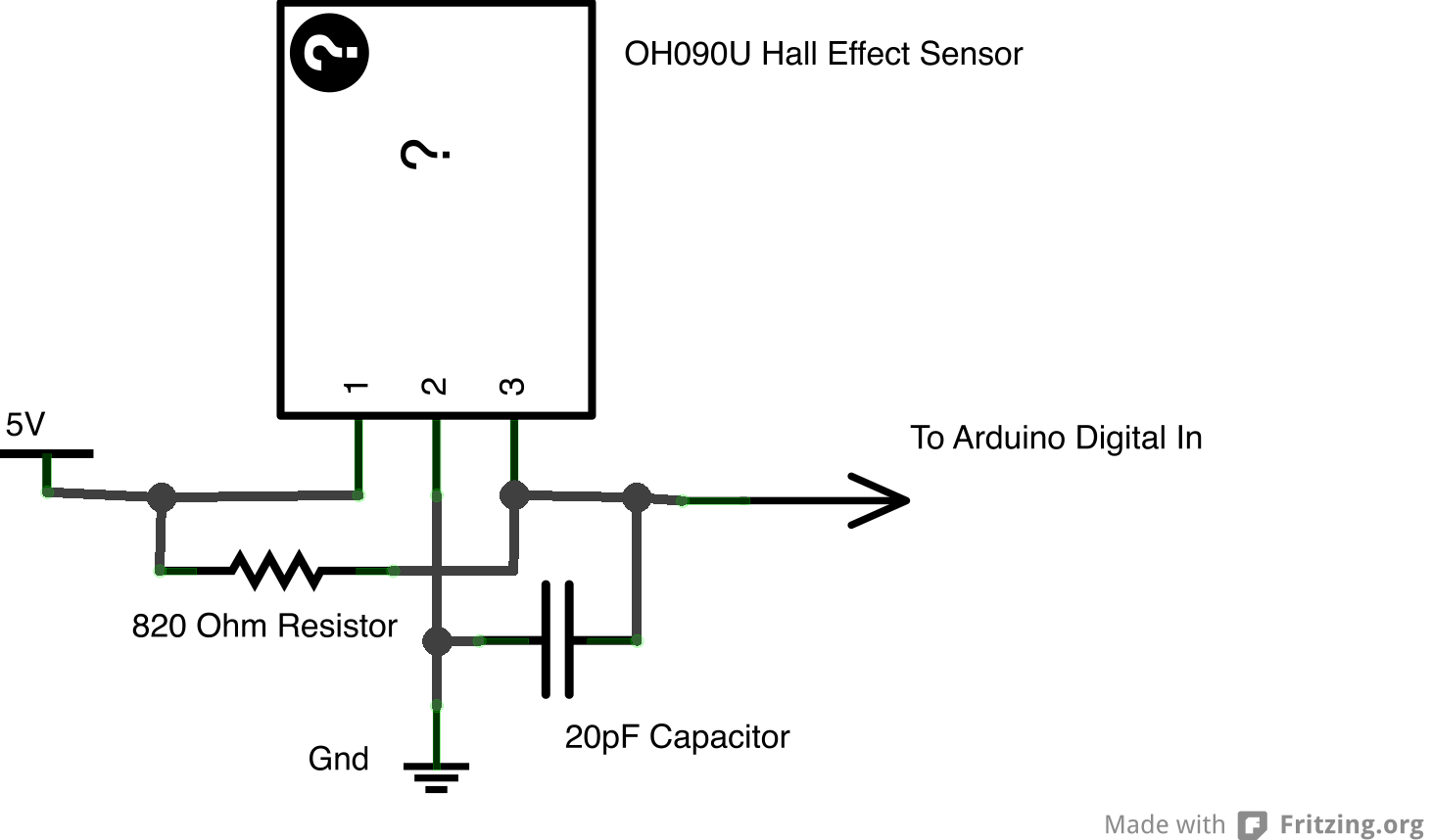
Moreover the wire is locked tight in upper part by a peg belonging to grey plate, and I had to cut that peg too. D1, D2 rectify power supply, C1 filters it. K1 and K2 are two opto-forks (marked S89, I didn`t found exact part type), one side contains an infra-red led, the other side a phototransistor.
Blade of propellar shape part can interrupt infrared beam of K1, K2, both or none, providing the four phases of the returned value. Since there are 4 blades, we obtain 16 steps per turn. IR leds receive power through R1 (about 5mA). The node be 🔗 External reference
Related Circuits
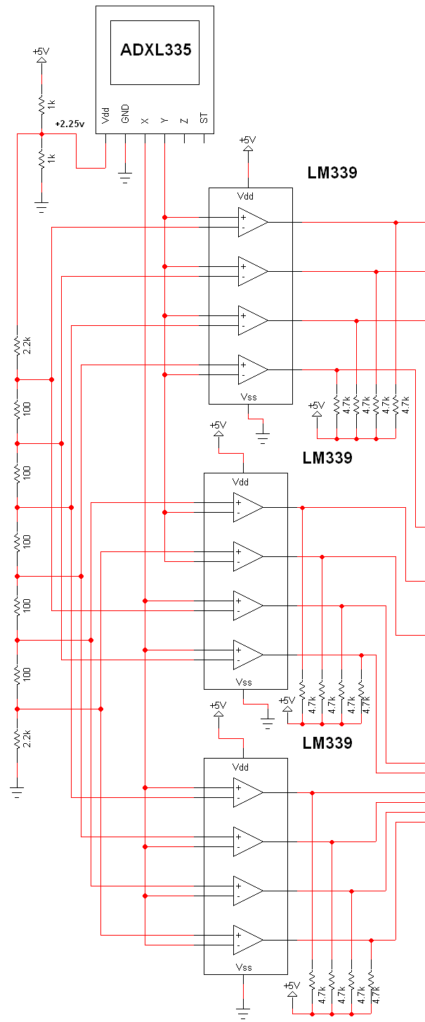
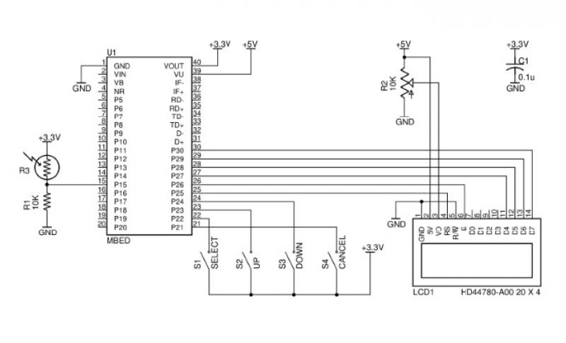
The schematic for this project is extensive, and the complete schematic is displayed below. It is divided into two sections: the analog and digital sections. The schematic illustrates the analog-to-digital conversion circuit, which includes 12 comparators—6 for the X-axis...
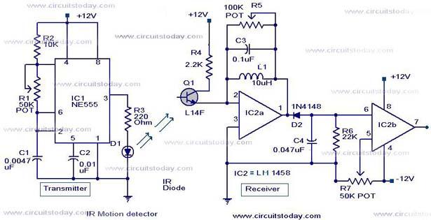
Infrared (IR) Motion Detector Circuit featuring a motion detector alarm and an infrared sensor. The circuit diagram and its operation are provided in detail. The infrared (IR) motion detector circuit is designed to detect motion within a specified range and...
In a class project, each student was required to select one of three technology platforms to design, simulate, prototype, and build, including PCB layout and ordering, all within a ten-week timeframe. The available platforms were: H-bridge Motor Controller, Infrared...
This acoustic sensor was originally developed for an industrial application (monitoring a siren), but it will also find many domestic applications. The sensor is designed with safety of operation as the top priority, meaning that in the worst-case scenario...
This issue features articles on various measurement and sensor-related embedded design projects. Readers are encouraged to attempt similar projects and share their results. Starting on page 14, Petre Tzvetanov Petrov describes a multilevel audible logical probe design. Petrov notes...
Although the Arduino effectively captures incoming sensor data, executing code typically in the microsecond range, challenges arose in transmitting data between the Arduino and Max. The data transfer speed was insufficient. The focus was primarily on creative project realization...