
Infrared Motion Detector Circuit-IR motion sensor circuit with motion detector alarm

The infrared (IR) motion detector circuit is designed to detect motion within a specified range and trigger an alarm when motion is detected. The core components of this circuit include an infrared sensor, a microcontroller or comparator, a power supply, and an alarm output device such as a buzzer or LED.
The infrared sensor operates by emitting infrared light and detecting the reflection of that light from objects within its field of view. When a person or object moves within this range, the sensor detects the change in the reflected infrared light and sends a signal to the microcontroller or comparator.
The microcontroller processes the signal from the infrared sensor. If motion is detected, it activates the alarm output. The alarm can be configured to be a sound (buzzer) or light (LED), depending on the application requirements. The circuit may also include additional features such as sensitivity adjustment and delay timers to prevent false alarms from minor movements.
Power supply considerations are critical for this circuit. Typically, a battery or DC power source is used to provide the necessary voltage and current to the components. Proper voltage regulation may be incorporated to ensure stable operation of the circuit.
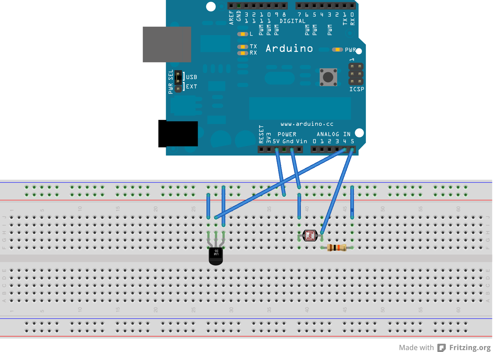
The schematic representation of the IR motion detector circuit will include the layout of the infrared sensor, the connections to the microcontroller or comparator, the alarm output configuration, and the power supply connections. The design should also indicate the values of any resistors, capacitors, or other passive components used to fine-tune the circuit's performance.
Overall, this infrared motion detector circuit is suitable for various applications, including security systems, automatic lighting control, and energy-saving devices, making it a versatile solution for detecting motion in a defined area.Infrared (IR) Motion Detector Circuit with motion detector alarm and infrared sensor.The motion sensor circuit diagram and working is given in detail.. 🔗 External reference
Related Circuits

A diesel tractor is equipped with a magnetic reed switch in the fuel tank to indicate low fuel levels. The switch remains open when fuel is present in the tank and closes when the fuel level drops below a...

The circuit employs two Light Dependent Resistors (LDRs) arranged in series with a separation of approximately half a meter. This configuration allows each LDR to detect the presence of a person entering or exiting the room. The processed outputs...

This simple and economical infrared model train detector circuit is designed specifically for hobbyists who want to incorporate a smart sensor to detect trains on their model railway track. The schematic diagram illustrates a straightforward configuration comprising an infrared...

Clipping is a significant issue that leads to distortion in amplifiers. It results in the amplitude level of a waveform dropping abruptly before it reaches its intended limit. This document presents a straightforward circuit designed to detect clipping in...
This device transmits data regarding the state of an office to Twitter, as it is deemed slightly more relevant than sharing similar information about a residence. It holds potential significance for biodiversity-related activities, especially when integrated with long-range WiFi...
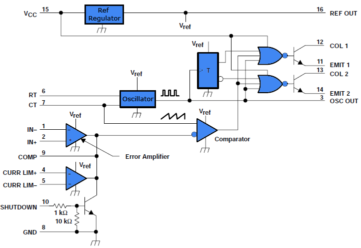
This document outlines a simple PWM (Pulse Width Modulation) DC to AC voltage inverter circuit based on the SG3524 integrated circuit. The SG3524 is a fixed frequency PWM voltage regulator control circuit that offers indifferent outputs suitable for both...