
Lesson Plan for Modulated Laser Laboratory
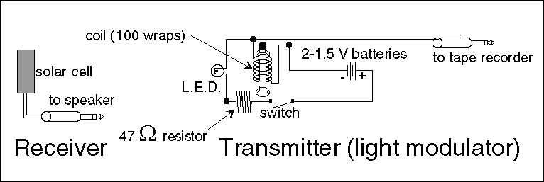
In this experimental setup, the primary components include an LED, a flashlight bulb, an induction coil, a solar cell, and an amplified speaker. The LED serves as the light source for modulating the sound signal, offering advantages over traditional incandescent bulbs due to its efficiency and directional properties. The induction coil plays a crucial role in managing the flow of current, enabling the conversion of sound waves into electrical signals and vice versa.
The process begins with the conversion of sound into electrical pulses using a microphone connected to the tape player. These electrical pulses modulate the LED's brightness, creating variations in light intensity that correspond to the sound waves. The light emitted by the LED is then transmitted through air or fiber optics to a solar cell, which captures the light and converts it back into electrical pulses.
The solar cell's output is fed into an amplifier, which enhances the signal strength before sending it to a speaker. The speaker then reproduces the original sound, completing the cycle of conversion from sound to light and back to sound. This method demonstrates the principles of communication via electromagnetic radiation, showcasing the versatility and effectiveness of using light for signal transmission in modern technology.
The experiment also illustrates the fundamental concepts of modulation and demodulation, essential for understanding how information can be transmitted over various mediums. The ability to manipulate electromagnetic waves for communication purposes is a key aspect of contemporary electronics and telecommunications.Electromagnetic radiation is used in communication. You are more familiar with radiowaves, microwaves, and TV signals. Visible light is also electromagnetic radiation and can be used to transmit a signal. It is a whole new technology called fiber optics. A discussion of this laboratory can be found in the Exploratorium Science Snackbook. We have m odified the snackbook`s "modulated laser" by substituting an LED (light emitting diode) for a flashlight bulb. By using an LED instead of a flashlight bulb, we can get a cleaner signal. Unlike incandescent light bulbs, the LEDs have a directional polarity. You must connect the positive and negative leads to them correctly, or they will not work. In this laboratory, you will convert sound into electrical pulses. The electrical pulses will be converted into rapid fluctuation in the brightness of a flashlight bulb.
This light will be transmitted through the air or fiber optics to a solar cell and converted back into electrical pulses. The electrical pulses will be fed into an amplified speaker and turned back into sound. The apparatus is shown in figure 1. "The induction coil acts as a short circuit for the direct current from the battery. As a result, when the flashlight is turned on, current flows through the coil and the lamp is lit. The induction coil acts as an open circuit for the alternating current from the tape player. As a result, the electrical pulses that would power the headphones must flow through the flashlight bulb.
The "sound vibrations" recorded on the tape are transformed into electrical vibrations that produce rapid fluctuation in the brightness of the flashlight bulb. These fluctuations are picked up by the solar cell and are turned into electrical pulses, which are amplified by the speaker or tape recorder and turned back into sound.
Laser beams, radiowaves, and flashlight beams are electromagnetic waves, not sound waves. In this Snack, these electromagnetic waves are modulated to carry the pattern of the sound waves. 🔗 External reference
Related Circuits

The IR photo transistor Q1 (Radio Shack 276-145A) or a similar component is connected to the set input (pin 6). It is essential to shield the photo transistor from direct light to ensure that the voltage at the set...

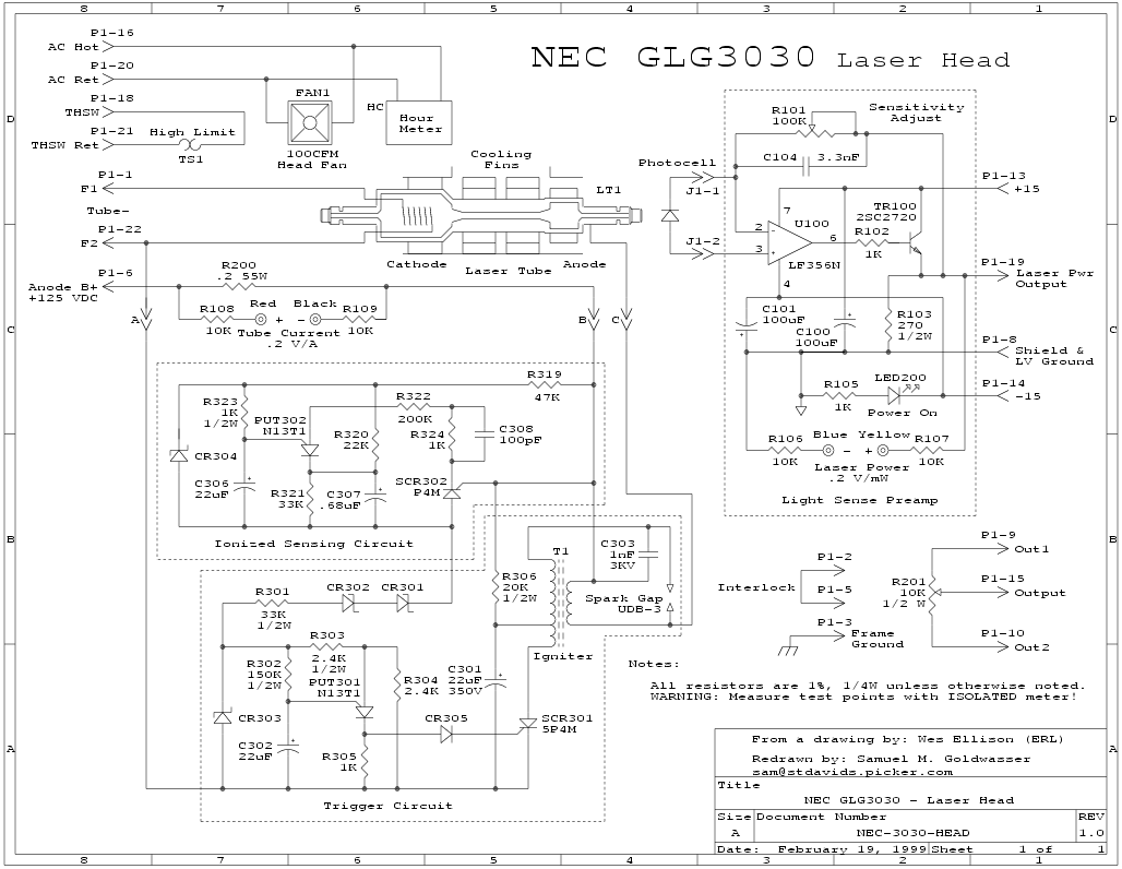
This chapter presents detailed schematics for various power supplies compatible with commonly available Ar/Kr ion tubes in the surplus market. It includes examples of commercial designs such as the Omnichrome 150R and 532 head, Lexel 88 and head, alongside...
The circuit is divided into two sections: the isolated external loop connected to the remote interface connector on the front of the power supply unit (PSU) and the non-isolated inner loop connected to the high-tension (AC line) supply. The...

This is a 50-watt audio power amplifier circuit based on the single IC STK4036II. A heatsink is required to prevent overheating of the IC. The amplifier circuit provides good sound quality at an affordable price and is easy to...
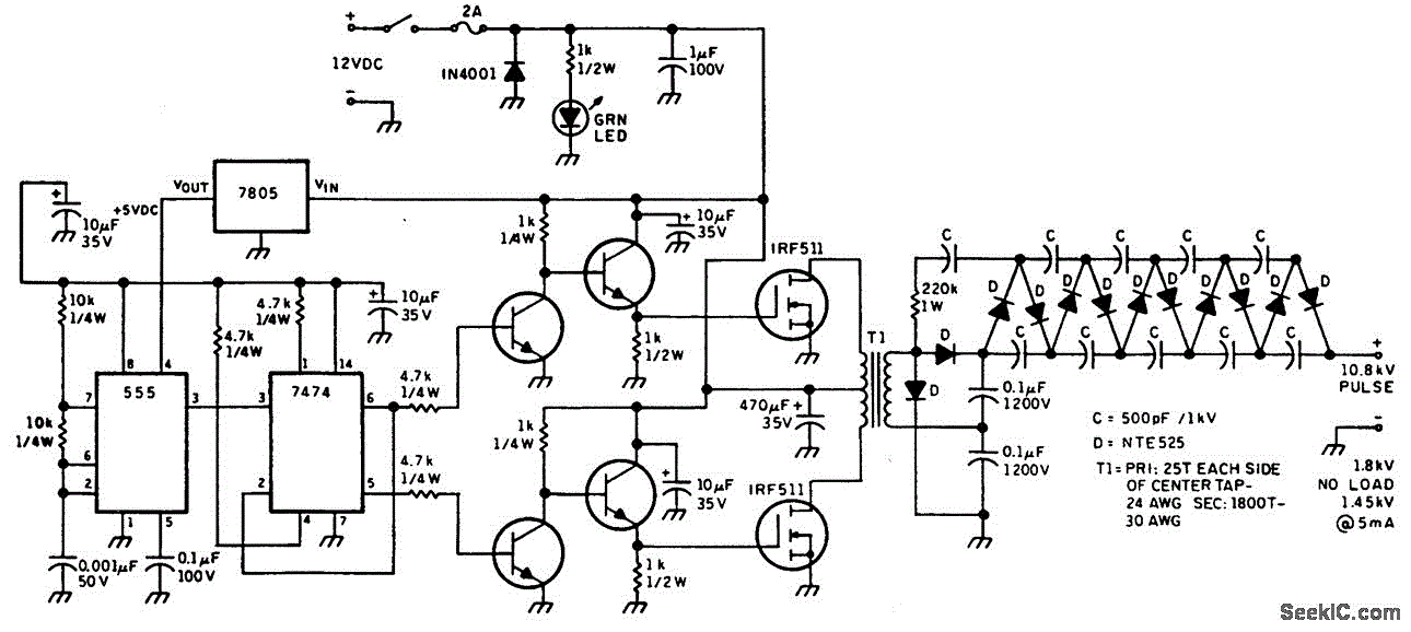
This figure illustrates a method for generating a momentary 10-kV voltage pulse to initiate plasma discharge across a laser tube. A diode voltage-multiplier circuit is connected in series with the main supply, obtaining its input power from one of...
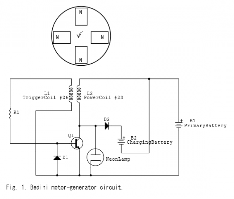
When the magnet approaches, the magnetic flux within the bifilar coil increases. An opposing magnetic flux is generated by the coil, resulting in an electromotive force (EMF) across inductors L1 and L2. The EMF across L1 applies a positive...