
Explanation of Bedini’s Pulse Motor and Generator

The described circuit utilizes a bifilar coil configuration, which consists of two closely wound coils that share a common magnetic core. The operation is based on electromagnetic induction principles. When a magnet approaches the coil, the change in magnetic flux induces an EMF in the coils. The resulting positive voltage at the base-emitter junction of transistor Q1 allows it to enter saturation, enabling a substantial current flow from the power source (B1) to the load. This current flow enhances the magnetic field in the coil, creating an opposing magnetic force that pushes the magnet away.
Upon the magnet's departure, the reduction in magnetic flux reverses the induced EMF across L1, applying a negative pulse to the base-emitter junction of Q1. This pulse causes Q1 to turn off, resulting in a rapid decrease in collector current. The collapse of the magnetic field in L2 induces a high voltage spike, which can be used to charge an additional energy storage element, such as battery B2. The interaction between the coils, the transistor, and the magnetic field exemplifies the principles of inductive coupling and energy transfer in electromagnetic systems. This circuit can be applied in various applications, including energy harvesting, magnetic field sensing, and electromagnetic actuation systems.When the magnet approaches, N flux inside the bifilar coil increases. An opposing flux is produced by the coil and an EMF is generated across L1 and L2. The EMF across L1 applies + voltage to B-E terminals of Q1 and turns it ON. Q1 saturates rapidly and a high current is withdrawn from B1. This current builds a strong magnetic field inside the coil. Since L1 and L2 share the same core, an opposing flux is produced by L1 and the magnet is pushed away.
As the magnet goes away, the flux inside the coil decreases. An EMF is induced across L1 that applies - pulse at B-E terminals and Q1 is turned OFF.
Consequently, collector current is cut sharply. As the magnetic field inside L2 collapses, a high voltage spike is produced by L2 that charges B2.
by 4beowulf7 - [email protected]
Related Circuits
This circuit generates a stable 1 kHz sine wave using an inverted Wien bridge configuration composed of components C1, R3, C2, and R4. It features a variable output, low distortion, and low output impedance to ensure good overload capability....
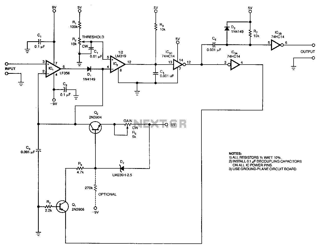
The output pulse width from the circuit is a linear function of the input pulse height. The circuit's input threshold can be set to discriminate against low-level pulses, while fixed components limit the maximum output pulse width. With a...
This is a simple function generator built around a single 8038 waveform generator IC. The circuit is capable of producing sine, square, or triangle waves within a frequency range of 20Hz to 200kHz. The function generator circuit utilizes the 8038...
The following circuit illustrates a stepper motor controller. This circuit is based on the PIC16F84A integrated circuit. Features: a transistor is utilized to drive the motor. The stepper motor controller circuit employs the PIC16F84A microcontroller, which serves as the central...
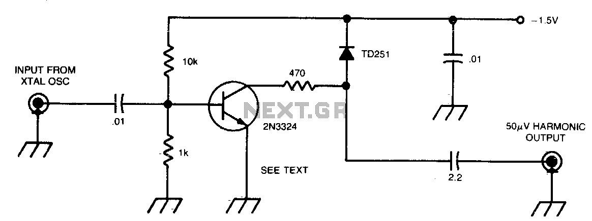
This circuit generates 50 µV harmonics at frequencies up to 1296 MHz, utilizing an input voltage of 0.5 to 1 V from a 100 or 1000 kHz crystal oscillator. By employing a germanium diode instead of a tunnel diode,...
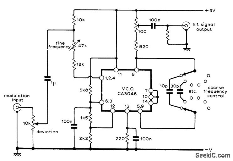
A sine-wave input can be applied to an RCA CA3046 transistor array configured as a voltage-controlled oscillator (VCO), which functions effectively as a low-distortion frequency modulation (FM) signal generator. When a sawtooth input is utilized, the same configuration operates...