
li ion white led driver by

The LT1618 is a versatile device designed for efficient LED driving applications. Its ability to operate with a wide input voltage range makes it suitable for various power sources, enhancing its applicability in portable devices and battery-operated systems. The integration of a current regulation feature allows for precise control over LED brightness, essential for applications requiring variable lighting conditions.
The PWM method for brightness adjustment is particularly advantageous, as it enables rapid changes in LED intensity without significant thermal output, thereby maintaining the efficiency of the circuit. When utilizing a DC voltage for brightness control, the option to eliminate the low-pass filter simplifies the circuit design, reducing component count and potential points of failure.
The output voltage configuration, managed by the resistive divider network (R1 and R2), is a critical aspect of the design that ensures safe operation. By limiting the maximum output voltage to 26V, the LT1618 is protected against potential damage that could occur from LED disconnection, an important consideration in robust circuit design.
The constant-current regulation mechanism is another vital feature, ensuring that the LED current remains stable at 20mA, which is crucial for maintaining consistent brightness and preventing LED degradation over time. The use of a 2.49Ω sense resistor to monitor current flow demonstrates a practical approach to achieving this regulation, allowing for efficient power management within the circuit.
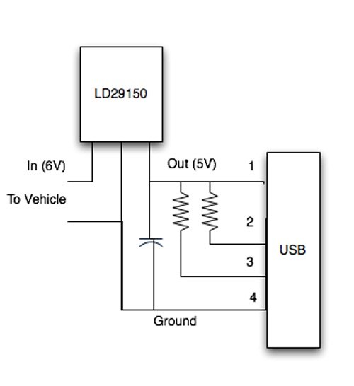
Overall, the LT1618 provides a highly effective solution for driving white LEDs, combining flexibility in input voltage, adjustable brightness control, and robust current regulation to meet the demands of various applications.In addition to providing an accurate input current limit, the LT1618 can also be used to provide a regulated output current for current-source applications. White LED drivers are one such application for which the LT1618 is ideally suited. With an input voltage range of 1. 6V to 18V, the LT1618 can provide LED drive from a variety of input sources, including two or more alkaline cells, or one or more Li-Ion cells. The circuit in Figure 7 is capable of driving six white LEDs from a single Li-Ion cell. LED brightness can be adjusted using a pulse width modulated (PWM) signal, as shown, or by using a DC voltage to drive the IADJ pin directly, without the R3/C3 lowpass filter. If brightness control is not needed, simply tie the IADJ pin toground. Typical output voltage with the LEDs shown is around 22V, and the R1, R2 output divider sets the maximum output voltage to around 26V to protect the LT1618 if the LEDs are disconnected.
The LT1618G ‚¬ s constant-current loop regulates 50mV across the 2. 49W sense resistor, setting the LED current to 20mA. 🔗 External reference
Related Circuits
How can a 1950 Studebaker be enhanced? By installing an iPod Nano in the dashboard. The team at MAYA Design created a touch-controlled sound system for this project, referred to as the "Nano-Baker" or "Stude-iPod," utilizing a pair of...
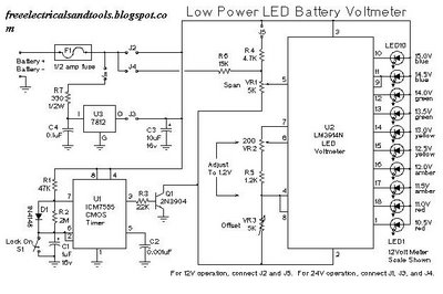
This is a low power voltmeter circuit designed for use with alternative energy systems that operate on 12V and 24V batteries. The voltmeter features an expanded scale that indicates small voltage steps within the 10 to 16 volt range...
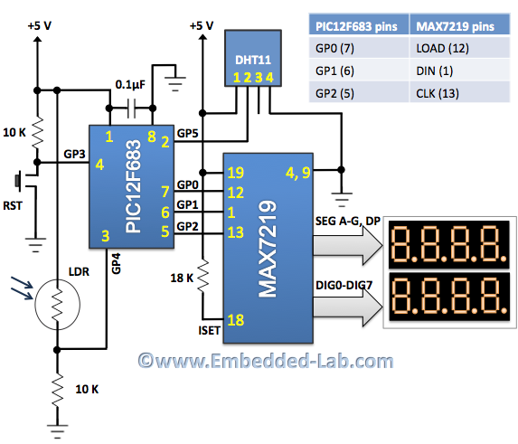
An automatic brightness adjustment is a closed-loop system that has the capability to assess ambient light and adjust the brightness of the display accordingly. The automatic brightness adjustment circuit operates by utilizing a light sensor, typically a photoresistor (LDR) or...
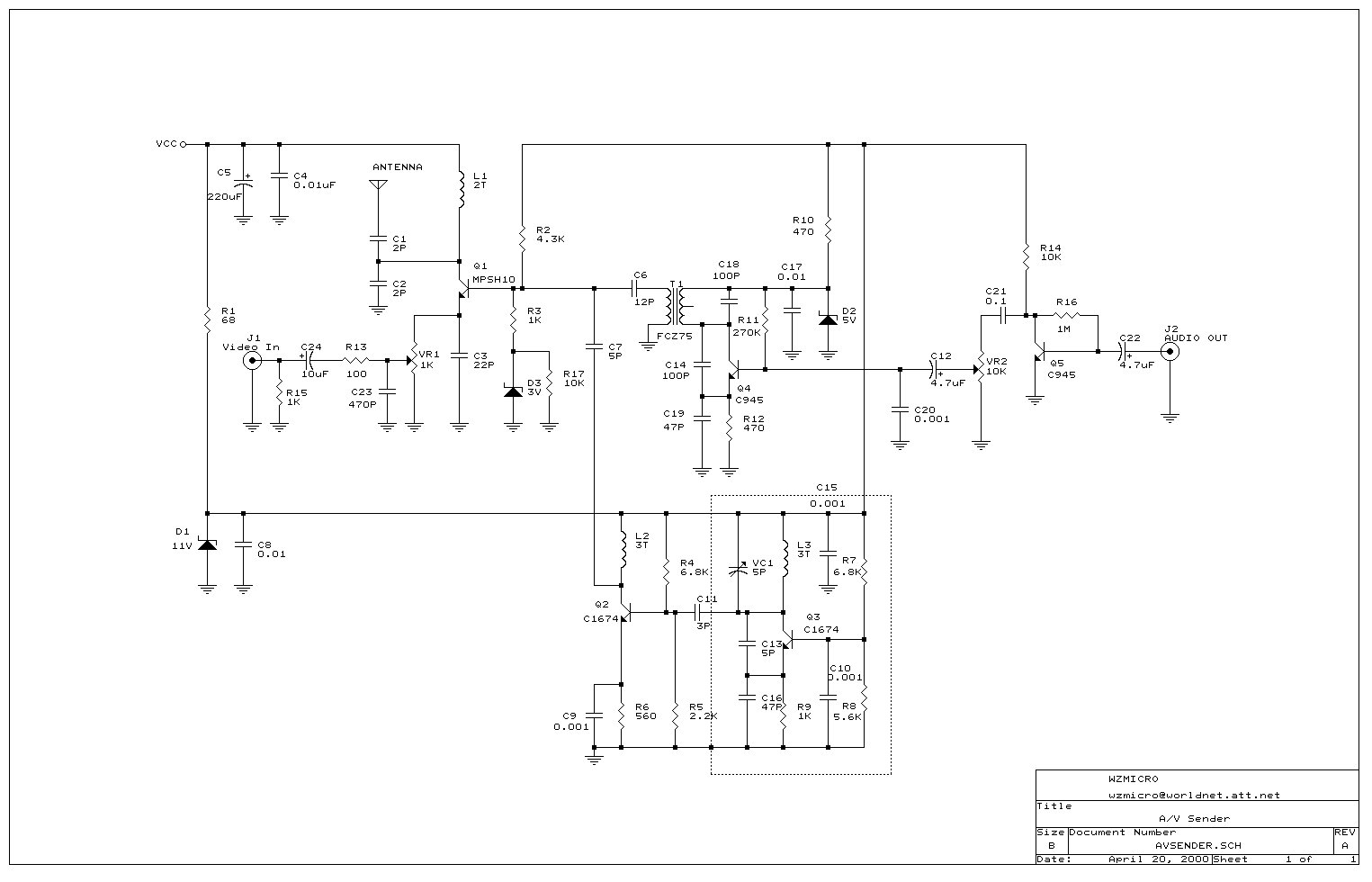
Wireless audio and visual transmission to a TV. The TV functions as a receiver, eliminating the need for a separate monitor. It can also be connected to a VCR or CCD camera, enabling the setup of a remote CCTV...

This circuit is designed to illuminate a single prototype railroad signal. It can be utilized for driving a model railroad signal, but it is intended solely for static displays and is not compatible with DCC systems, computers, or similar...
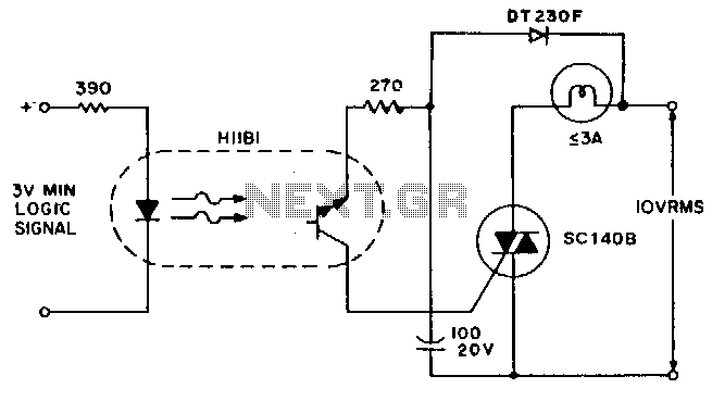
A simple solid-state relay circuit drives the 10-Vac telephone indicator lamps from logic circuitry while maintaining complete isolation between the 10-V line and the logic circuit. The described circuit utilizes a solid-state relay (SSR) to control 10-Vac telephone indicator lamps...