
Railroad Signal Driver
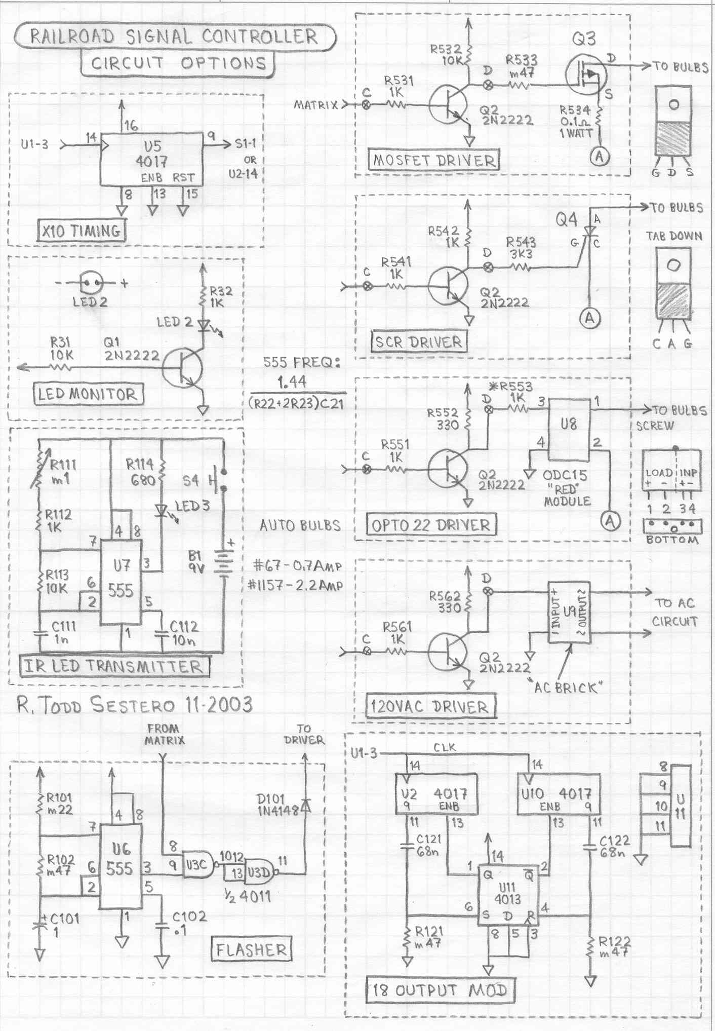
The circuit's architecture comprises three main components. The oscillator section, utilizing the 555 timer chip (U1), is configured as an astable multivibrator. This configuration ensures continuous oscillation, producing a square wave output at pin 3 with a duty cycle of approximately 40%. Proper attention must be paid to the power connections, as they are located on non-standard pins. The resistors R21, R22, and R23, in conjunction with capacitor C21, define the oscillation frequency and period of the output signals.
The counter/decoder section employs a CMOS 4017 chip, which provides ten decoded outputs. Each output transitions to a high state in a positive logic format, facilitating straightforward decoding with diodes. This simplicity allows for effective signal control, as each output can be directed to control specific aspects of the signal display.
The driver circuits are responsible for illuminating the respective bulbs based on the outputs from the counter/decoder. The number of driver circuits required is contingent upon the complexity of the signal being controlled. For instance, a simple three-color light signal necessitates three drivers, while a more complex installation, such as a full B&O CPL signal, may require up to ten drivers to accommodate all aspects and markers.
In summary, this circuit offers a robust solution for controlling railroad signals, leveraging the reliability of the 555 timer and the flexibility of the CMOS 4017 for aspect management. Its design allows for easy adaptation to various signal types and configurations, making it suitable for model railroad enthusiasts and static displays alike.This circuit can be used for lighting a single (prototype) railroad signal. You could use this to drive a model railroad signal, but only if it is for a static display - for this circuit is not designed to be interfaced with anything. DCC systems, computers, or otherwise. I`ve used variations of this circuit for over 25 years to control many other things around my house, and they never (ok, very rarely) fail me. It relies on the venerable 555 timing chip. This circuit is simple and reliable. I`ve used small microprocessor chips do to similar things in the past, but they never seem to last as long before something needs to be replaced. It also eliminates the need buy a programmer, to write a program, and then uploading that program into the microprocessor.
Email me if you have any questions. 0. 2 For the purposes of this write-up, the schematic and circuit description are for a Pennsy dwarf position light that can display four aspects: slow clear, slow approach, restricting, and stop signal. The common bulb #4 stays lit for the first three aspects. For restricting, #4 goes out, and #1 and #3 light up. This is why, later on when we get to the description on the driver circuit, we wire bulb #4 to the normally closed contact of the relay.
The circuit however, can be used on any signal, even a full blown B&O CPL with all four colors and six markers (you`ll just need 10 driver circuits). 0. 3 Some of the circuits used for the individual circuits descriptions will differ slightly from that of the final single circuit at the bottom of the page.
1. 1 The signal controller circuit is pretty simple. I can be broken down into three sections, as shown to the right: 1) the oscillator, 2) the counter/decoder, and 3) the driver circuits. 1. 2 As mentioned before, the oscillator (aka: clock) uses a 555 timer chip. It is wired as an astable multivibrator (it just sits there and oscillates till time itself stops). It`s a standard circuit, and pretty much right out a data book. 1. 3 The counter/decoder circuit is also a textbook example of the use of a CMOS 4017. The decoded outputs of the 4017 go high, so it`s positive logic makes for simple decoding using diodes.
A single 4017 has ten outputs. 1. 5 If you want to build this controller in its simplest form, you only need what`s in the block diagram. With this minimum configuration, you have up to 10 aspects that can be displayed. The number of output driver circuits you need to build will depend on the number of different aspects your signal requires.
For instance, a standard three color light signal needs three output drivers. A searchlight signal only needs two drivers. A Pennsy position light signal needs as few as two or three, depending on how many positions it has, but can go up to five drivers if you have a full head and want to display the more obscure aspects like lower the pantograph . If you are lucky to have two Pennsy signal heads, there are 13 aspects possible, 15 if you include the two obscure ones (which I have never seen).
There are 16 aspects for a full B&O CPL signal (including the 6 markers lamps), and two of the aspects employ flashing markers. And lastly, depending on the road, there are around 12 aspects for a full 3 head color light installation.
2. 1 U1 is a 555 timer chip. It`s been around almost forever. FYI-the output at pin 3 has about a 40% duty cycle (in other words, it is on (or high) for approx 40% of the cycle, or period). Be careful wiring the power connections (+Vcc and ground), as they are on non standard pins! R21, R22, and R23, along with C21, determine the oscillating frequency, or period. One period is how long each output of the 401 🔗 External reference
Related Circuits
The DC motor driver circuit depicted in the images can be utilized for controlling DC motors, allowing for bidirectional rotation and adjustable speed. This straightforward circuit is constructed using a 741 operational amplifier (op-amp) as a voltage comparator, along...
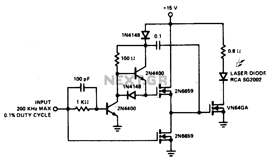
A faster driver can supply higher peak gate current to switch the VN64GA very quickly. The circuit uses a VMOS totem pole stage to drive the high power switch. The described circuit employs a high-speed driver to enhance the switching...
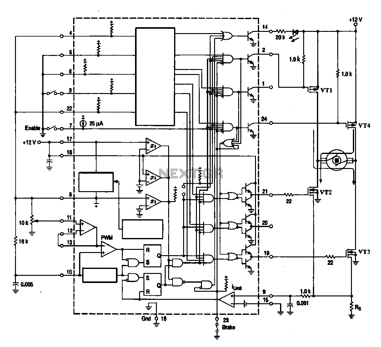
A DC brush motor driver circuit diagram utilizing the MC33035 chip is presented, illustrating a typical configuration for driving a straight DC brush motor. The circuit incorporates a field-effect transistor (FET) bridge driver setup. When transistor VT3 is activated,...
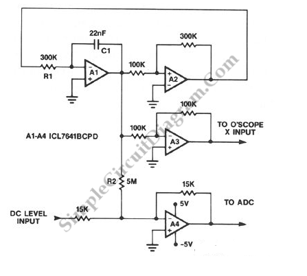
A symmetrical millivolt peak-to-peak triangle waveform can be generated by the circuit illustrated in the schematic diagram below. This circuit is equipped with... This circuit employs an operational amplifier (op-amp) configured in an integrator setup to produce a triangle waveform. The...
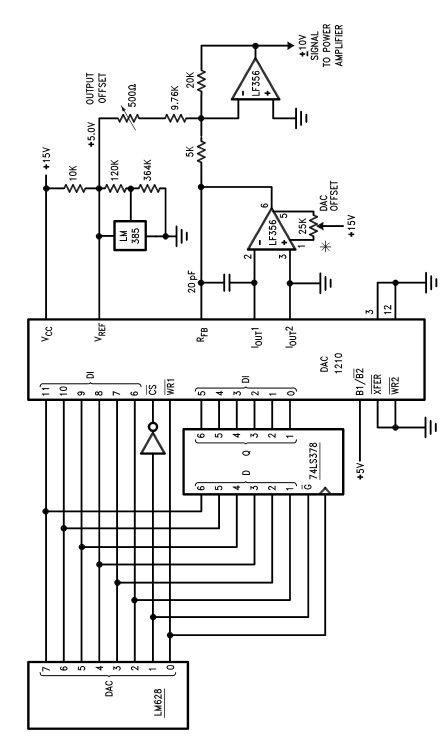
The LM628 and LM629 dedicated motion-control processors can be utilized to design various applications involving DC and brushless DC servo motors, as well as other servomechanisms. The power path of this electronic project, which functions as a motor driver,...
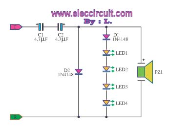
The circuit detects a ringing signal tone and provides both light and sound indicators. It is user-friendly and of good quality, and it does not require a power supply to operate, functioning solely to detect the ringing signal. The described...