
Light Activated Relay with 555 Circuit
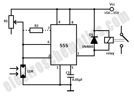
The light-activated relay circuit operates on the principle of comparing the voltage levels at the threshold pins of the 555 timer. The circuit is designed with two reference voltage levels: one at 1/3 Vcc and the other at 2/3 Vcc. The LDR serves as a variable resistor whose resistance decreases with increasing light intensity, allowing for precise control over the relay operation. The inclusion of the potentiometer R1 allows fine-tuning of the circuit's sensitivity to light changes, ensuring reliable performance in varying ambient light conditions.
In operation, when the ambient light level drops, the resistance of the LDR increases, causing the voltage at the threshold pin to rise. Once this voltage exceeds 2/3 Vcc, the output of the 555 timer switches from high to low, energizing the relay coil. This action can be used to trigger an alarm or turn on a light, depending on the application. Conversely, when the light level increases, the LDR's resistance decreases, and the voltage at the threshold pin drops below 1/3 Vcc, returning the output to a high state and deactivating the relay.
The addition of resistor R2 is a crucial design aspect that enhances stability by adjusting the hysteresis of the circuit. This resistor ensures that the relay does not rapidly switch on and off due to minor fluctuations in light levels, which could cause unwanted activation or deactivation. Careful selection of R1 and R2 values, along with the appropriate relay specifications, will ensure the circuit functions effectively in its intended application. The circuit can be powered using a suitable DC power supply that matches the relay's voltage rating, ensuring safe and reliable operation.This light activated relay circuit presented here uses the 555 timer IC and a light dependent resistor or LDR to form a light sensitive relay in an intruder alarm system or for switching on a lamp at Sun set and off at Sun rise. Potentiometer R1 value must be chosen and then adjusted that under normal conditions when the light is falling on the LD
R the voltage across the LDR is less than 1/3 of Vcc. The output of the 555 IC is high now. The actual value of R1 will depend on the resistance of the LDR. When the light fades or is interrupted by an intruder, the voltage across it rises above 2/3 of Vcc, tripping the IC flip-flop. The output goes low activating the relay. When the light is restored, voltage falls below 1/3 of Vcc, again tripping the flip-flop causing the output to go high and the relay drops.
The difference of 1/3 of Vcc between turning on and turning off voltages prevents relay chatter. This differential can be reduced by connecting a resistor R2 shown dotted in the schematic. Its value is about one and a half times of the LDR resistance in its illuminated condition. Use a 6V or 12V relay with a current of 200mA max. 🔗 External reference
Related Circuits

This 15V variable power supply electronic project is designed using 2N3055 transistors. The output voltage of this variable power supply can be adjusted in the range between 1.5 and 15 volts. This 2N3055 15V variable power supply can provide...
This page will be updated as material becomes available. This new system will essentially replace the original BCD design, which was created by WB6IGP and N6IZW and was featured in the ARRL UHF/Microwave Project Manual. Their work was later...
The 555 timer IC was first introduced around 1971 by the Signetics Corporation as the SE555/NE555 and was referred to as "The IC Time Machine." It was the first commercially available timer IC, providing circuit designers and hobbyists with...
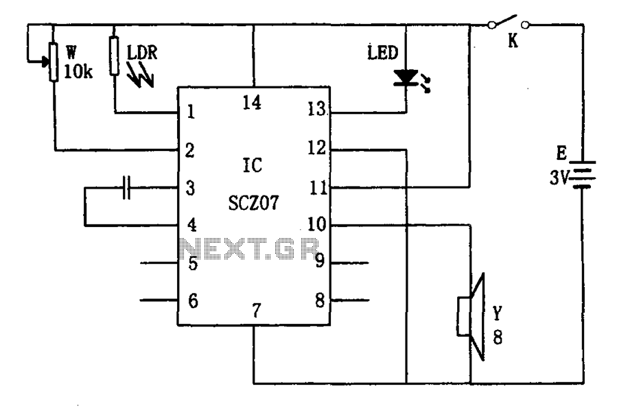
The weak light alarm circuit is illustrated in the figure. The oscillator circuit's core component is the SCZ07. The input signal is controlled by a potentiometer (W) and the output signal is processed by a photoresistor (LDR). The circuit...

This circuit design was used to switch on device via a LED photocell arrangement (optocoupler) using components R1, C1, D1 and Q1. It produces a delay on powering up to ensure correct sequencing of certain equipment. A very simple...
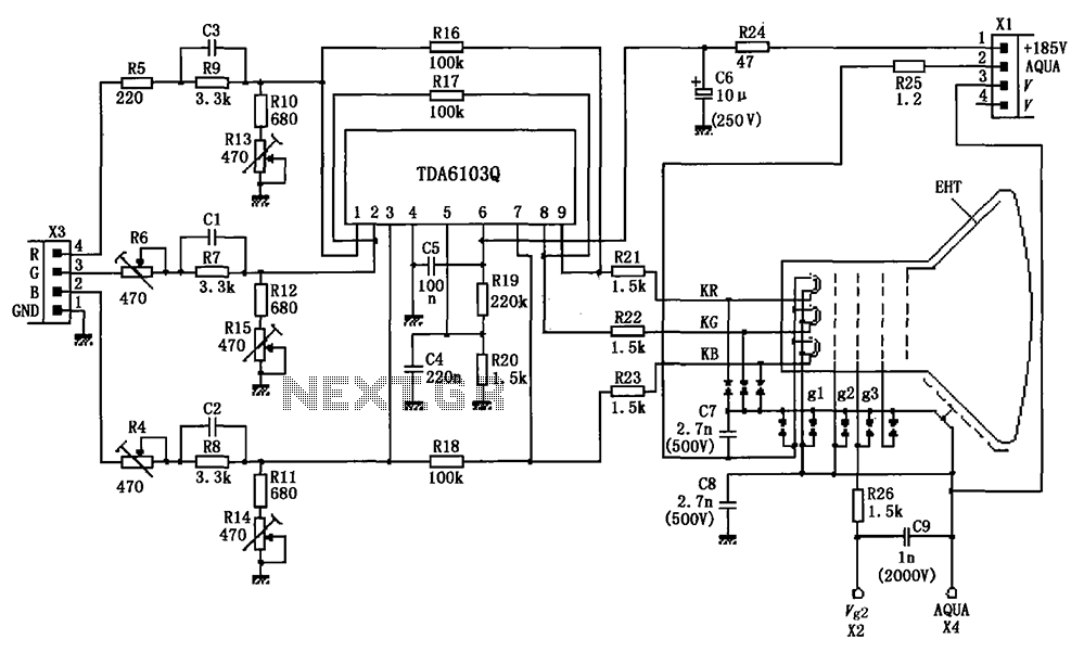
The circuit depicted in the figure integrates the TDA6103Q with a color picture tube, illustrating its practical application. The red, green, and blue (R, G, B) input signals are received from the input socket X3 and processed through a...
Warning: include(partials/cookie-banner.php): Failed to open stream: Permission denied in /var/www/html/nextgr/view-circuit.php on line 713
Warning: include(): Failed opening 'partials/cookie-banner.php' for inclusion (include_path='.:/usr/share/php') in /var/www/html/nextgr/view-circuit.php on line 713