
Light Alarm Circuit
of a room will go off. An example of where we could use this circuit is in the following real-world example. We could place this device in a very dark area such as the drawer of a cabinet. Let`s say we have a lot of valuables which we want to protect in a chester drawer such as jewelry. And we regularly keep this drawer closed. Being closed, no light enters and the circuit is in enclosed in a dark area with no light. Under these conditions, the alarm does not go off because it is not exposed to light. However, say, if a thief breaks into the house and opens this drawer either during the day or at a night, shining a flashlight into the drawer. Now exposed to light, the circuit will trigger and buzz an alarm. So the housekeeper can know if someone has broken in by hearing this device. This one possible application of this light alarm circuit we will build. What we will use for this circuit is a 200KG photoresistor. Photoresistors are also called light-dependent resistors (LDRs). This can be obtained at digikey at the following link: Digikey- 200KG Photoresistor. If you don`t have a 200KG photoresistor, just make sure to use one that has a dark resistance of 100KG or greater.
A photoresistor is a resistor whose resistance changes according to the amount of light that it is exposed to. When exposed to total darkness, the photoresistor`s resistance is very high. This is called its rated dark resistance. For example, in our case we are using a 200KG photoresistor. This means that when exposed to total darkness, its resistance will be around 200KG . As the photoresistor is exposed to increasing amounts of light, its resistance begins to drop and drop significantly.
There is another rating on the datasheet labeled cell resistance @ illuminance. This is the resistance that the photoresistor will drop to when exposed to bright light, typically 10 lux. So a photoresistor is basically a device that gives off very high resistance at dark light levels and low resistance at high light levels.
Being that it does this, it acts as a sensor for light, or a photosensor. When exposed to a darkly lit area such as the insides of a chester drawer, the resistance will be very high. Since the resistance is so high, practically no current will flow through the circuit, so nothing turns on.
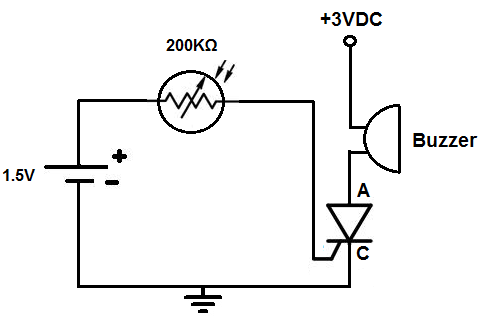
If the circuit is exposed to light, then the resistance drops significantly, allowing sufficient current to be able to flow which allows electronic components to turn on. Like a transistor, when the SCR receives sufficient voltage at its gate terminal, it conducts across from anode to cathode.
Without this voltage at its gate, no current can flow from anode to cathode. With this gate voltage, current can flow and power the load connected to the anode of the SCR. However, unlike a transistor, a SCR is different in that once it receives sufficient voltage at its gate, it conducts indefinitely from anode to cathode- unless power is disconnected from the anode. So while a transistor needs ongoing current at its base or gate terminal to conduct current across its junction, an SCR only needs to be triggered once to remain on.
Thus, it acts like a latching circuit in that once it is turned on, it latches on and stays on. Looking at the above SCR, with it turned to its back surface, the pin to the leftmost is the gate terminal, the middle pin is the anode, and the rightmost pin is its cathode. The photoresistor will be connected to the gate of the SCR. When the light increases to a certain level, the resistance drops, allowing current to flow through and trigger the gate of the SCR.
The SCR, then triggered, will then turn on the load connected to it, which in our case is a buzzer or an LED. In a darkly lit area, the photoresistor will offer very high resistance, near its rated value of 200KG .
At this resistance, practically no current flows so the SCR gate does not get triggered. However, when the photoresistor is exposed to a significant amount of light, its resistance drops significantly. Enough current now flows through the circuit to trigger the gate of the SCR. Once the gate of the SCR is triggered, current now flows across from its anode to cathode and turns on the buzzer.
Once triggered, the SCR stays on, just like an alarm, stimulating an alarm circuit. Different variations can be done for this circuit. If you don`t want a buzzer to go off but instead want an LED to light, swap out the buzzer with an LED. But for an LED, make sure to add about a current-limiting resistor, of about 200G -400G . You can add device that you want to go off once the SCR is triggered. Customize the circuit to suit your preferences. Also if you want to see a variation of this circuit which both lights an LED and sounds a buzzer off, see Light Alarm Circuit (LED and Buzzer go off).
This is the same circuit as above, only with a buzzer placed in parallel with the LED. 🔗 External reference
Related Circuits

Pressing the START pushbutton activates either the headlights or spotlights for a specified duration. After 1 minute, determined by R1 and C1, the lights will turn off as the NE555 timer completes its cycle. The circuit utilizes a NE555 timer...
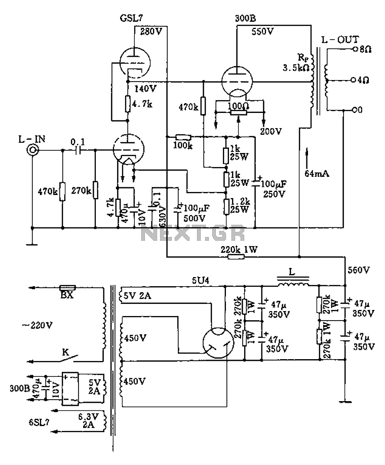
The 300B tube single-ended Class A amplifier circuit is as follows: The 300B tube single-ended Class A amplifier is a high-fidelity audio amplification circuit that utilizes a 300B vacuum tube as the primary amplification element. This design is characterized by...
The objective of this project was to design a small portable mixer powered by a 9V PP3 battery while maintaining performance quality. The mixer consists of three main modules that can be varied in number and can be adapted...
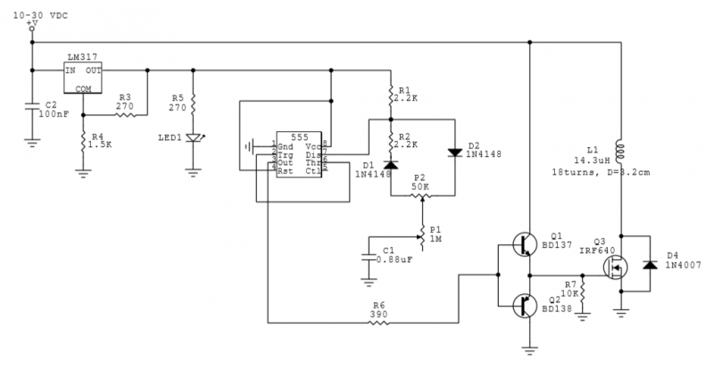
This circuit utilizes a 555 Integrated Circuit (IC) to generate a pulsed magnetic field, which can be employed for pulsed electromagnetic field (PEMF) therapy. The human body is affected by natural magnetic fields, including the Earth's magnetic field, geomagnetic...
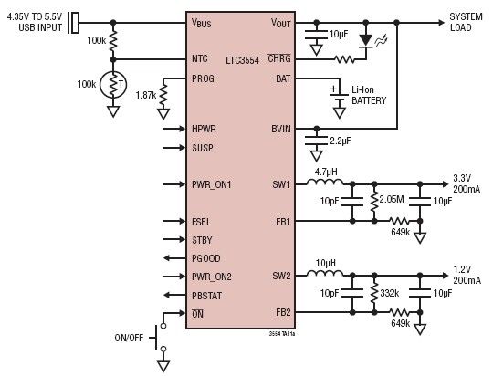
This micropower multifunction power management integrated circuit (PMIC) is designed using the LTC3554, manufactured by Linear Technology Corporation. It serves as a solution for portable Li-Ion Polymer battery-based applications. The LTC3554 integrates a USB-compatible linear PowerPath manager, a standalone...
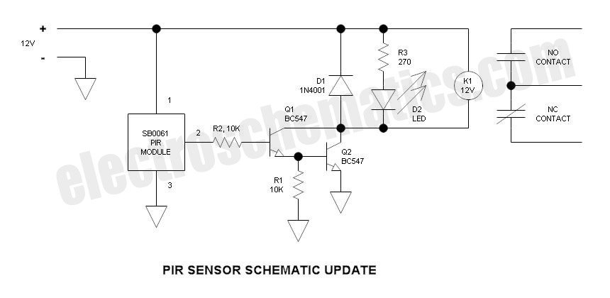
This is an update to Mr. Hareendran's PIR Sensor Security Light circuit. It has a limitation that restricts the relay voltage to approximately 3.3V. While this may work with some 5V relays, it is not compatible with all. The...