
Security Light & Switch with PIR Sensor Update
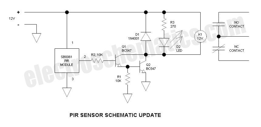
The described circuit utilizes a PIR (Passive Infrared) sensor to detect motion and activate a relay-based lighting system. The change from a common collector to a common emitter configuration enhances the voltage output capability, allowing for better compatibility with higher-voltage relays. By employing a 12V relay coil, the circuit can be more effectively integrated into existing systems that may utilize higher voltage supplies, while still accommodating lower voltage relays with the appropriate resistor in series to limit current.
The use of a Darlington pair (Q1 and Q2) provides a high current gain, which is beneficial for driving the relay without requiring a significant input current. The design also incorporates a back diode (D1) to protect against voltage spikes caused by the relay coil's inductive load when the relay is deactivated. This is a critical aspect of relay design, as it ensures the longevity of the transistors and other components in the circuit.
The choice of resistors (R1 and R2) is essential for proper biasing and stability of the transistor stages. R1 not only helps with leakage current management but also plays a role in the turn-off characteristics of Q2, which is vital for ensuring that the relay does not chatter or respond erratically to transient signals. R2 controls the base current to Q1, thus influencing the overall sensitivity of the motion detection.
The recommended operating voltage range (9 to 12V) is practical, as it provides ample headroom above the dropout voltage of the regulator, ensuring consistent performance of the entire circuit. Overall, this updated design presents a more robust solution for motion-activated lighting, with considerations made for component selection and circuit efficiency. Future iterations could explore additional features such as adjustable sensitivity or integrated timers to enhance functionality.This is a simple update to Mr. Hareendran`s PIR Sensor Security Light circuit. It has a shortcoming limits the relay voltage to approximately 3. 3V. While this may function with some 5V relays, it will not function with all. The nature of an emitter follower Darlington forces the output voltage to be two junction drops below the base drive voltage plus a small voltage drop across R1. In keeping with the spirit of his design, I retained the Darlington arrangement, and the transistor type number however, I changed the transistors from common collector to common emitter configuration, and connected the relay between the collector output and the positive rail. The relay now utilizes a 12V coil to use an existing 5V relay, simply add a resistor in series with the coil whose value is scaled up from the coil resistance.
Also, I connected the LED across the relay coil rather than powering it via the 2nd relay contact this way, only one form C relay contact is required thus making the relay less expensive of course it can be done either way. I eliminated some additional, unneeded components. When motion is detected, the output (pin 2) goes to 5V and current flows through R2 to the base of Q1.
The emitter current of Q1 becomes the base current of Q2 the current gain of a Darlington is the hFE squared or about 10, 000 to 50, 000 (very high). This easily provides adequate drive current for the relay. R1 provides a means of conducting any potential leakage in Q1 to common and also helps Q2 to turn off faster.
D1 is the back diode that circulates the relay coil current when Q1 & Q2 turns off thus preventing a damaging voltage transient. No, I did not build and test this one I just happen to know from experience that this circuit will work OK if the circuit was new to me, I would definitely Protoboard and test because Murphy may be lurking somewhere.
Murphy`s Law states that anything that can go wrong will go wrong Such is true as I have proven it numerous times. Supply voltage is roughly 5 to 20V as indicated by both the SB0061 module specifications and the BISS0001 IC application example.
I believe that it is typical for such modules to include a 7805L voltage regulator. The only confusion factor is how it works at 5V due to the drop-out voltage of the voltage regulator. This would reduce the regulated voltage to perhaps 3. 5V or so. As a result, I would recommend simply running it at 9 to 12V. Also, there is no standard 5V battery. I was just wondering that maybe in the future, you could publish a DIY circuit about the PIR sensor, It would be interesting, since it would the a major part of a PIR circuit.
🔗 External reference
Related Circuits
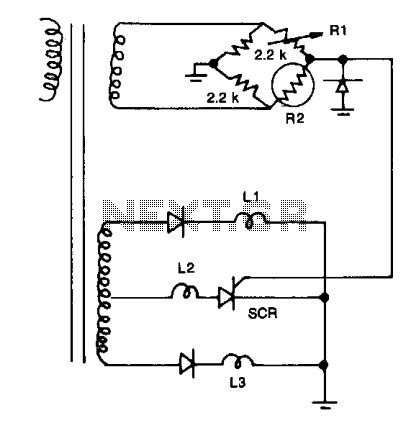
Resistors R1, R2, and the two 2.2 kΩ resistors form a bridge circuit. R2 is a thermistor, and R1 sets the temperature at which L2 lights. Lower or higher temperatures light L1 or L3 to indicate an over- or...
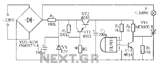
The H1.9811 single-channel flash control integrated circuit from Wuxi Love Core Microelectronics Co., Ltd. is designed for controlling flashing warning lights in road barricades. It features an integrated internal RC oscillator, frequency divider, output buffer amplifier, shaping circuit, and...
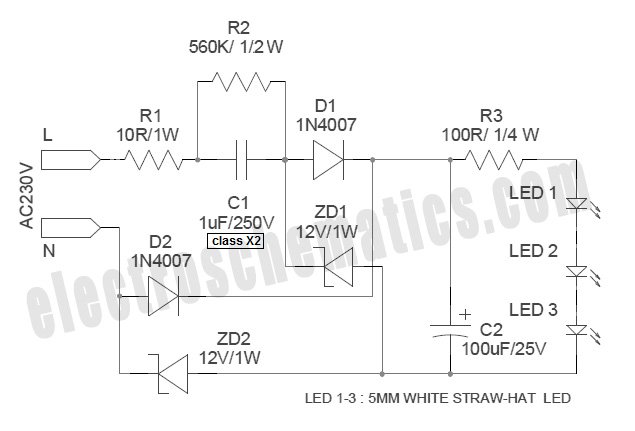
White Light Emitting Diodes (LEDs) now available can serve as a strong alternative to incandescent lamps in lighting applications. Today's White LEDs are... White Light Emitting Diodes (LEDs) represent a significant advancement in lighting technology, offering energy efficiency, longevity, and...
This project schematic illustrates an LM741 dark sensor relay switch circuit. The circuit is designed to activate a relay switch in the absence of light on the surface of a Light Dependent Resistor (LDR). The LM741 operational amplifier is utilized...
The handheld mini light beam receiver features a small solar cell on the left side, with various components visible on the circuit board through a transparent lid. On the right side, there are sockets for headphones and a crystal...
A newcomer has entered the field after completing several repairs and minor upgrades on tube amplifiers, including re-capping and addressing bias issues. The process of repairing and upgrading tube amplifiers involves several critical steps to ensure optimal performance and reliability....
Warning: include(partials/cookie-banner.php): Failed to open stream: Permission denied in /var/www/html/nextgr/view-circuit.php on line 713
Warning: include(): Failed opening 'partials/cookie-banner.php' for inclusion (include_path='.:/usr/share/php') in /var/www/html/nextgr/view-circuit.php on line 713