
Pulsed Magnetic Field Therapy (PMFT) Circuit
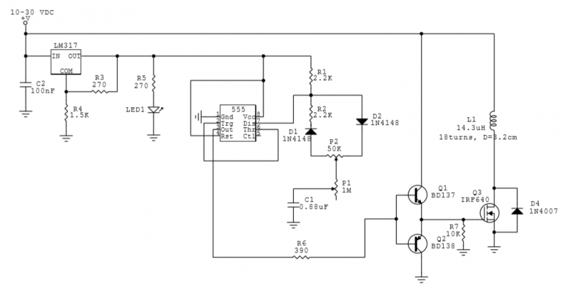
The circuit employs a potentiometer P1 with a resistance of 1 MΩ and a second potentiometer P2 with 50 KΩ. Resistors R1 and R2 are both set to 2.2 KΩ. A capacitor C1 is calculated to be 0.88 µF for a maximum frequency of 30 Hz, achieved by connecting four 220 nF capacitors in parallel. For a potentiometer setting of P1 at 1 MΩ, the minimum frequency is 1.5 Hz. The pulse width can be adjusted from approximately 1.5 ms to 31.5 ms using P2, allowing for a duty cycle variation from about 5% to 95% across the frequency range.
The field coil has a radius of 1.6 cm and consists of 18 turns, resulting in an inductance of 14.3 µH. The supply current is approximately 0.4 A at a 5% duty cycle and increases to about 4.8 A at a 95% duty cycle.
To calculate the magnetic field strength produced by the coil, it is important to note that the magnetic field of a circular coil cannot be expressed in a closed form except along its axis. When the origin of the coordinates is positioned at the center of the coil, and the z-axis is aligned with the coil's axis, the magnitude of the magnetic flux density B can be determined, which points in the z direction.
This circuit and its associated parameters provide a comprehensive approach to generating therapeutic pulsed magnetic fields, which may have beneficial effects on cellular function and overall health.Here is a simple circuit based on 555 IC that generates a pulsed magnetic field. You may use this field for pulsed magnetic field therapy. Human body is influenced by natural magnetic fields such as Earth’s magnetic field, fields due to geomagnetic storms, magnets, and magnetic rocks etc. Pulsed ELF magnetic fields (PEMFs) help cells to maintain their health (energy production, removing waste, self-repair, and regeneration) and cause motion of ions and electrolytes in cells and tissues.
PEMFs remove stress, accelerate healing, and slow aging process. Stress exhausts body and lowers the cell’s membrane potential which is usually 70 to 90 mV. The cell dies if this potential drops to zero level. A cell uses 50% of its energy to maintain this potential. PEMFs help building this membrane potential. High-intensity PEMFs (very short and strong magnetic pulses like lightning) destroy cancer cells. Suggested PEMF frequencies are between 1-50 Hz.
Here is the circuit that generates pulsed magnetic fields from about 1.5 Hz to 30Hz.
Since it’s difficult to find a suitable potentiometer, I select P1=1MΩ and P2=50KΩ initially. I also assume R1=R2=2.2KΩ. C1 is calculated as 0.88µF for max f =30Hz. Four 220nF capacitors are connected in parallel to form 0.88µF. For P1=1MΩ, min f =1.5Hz. Pulse width can be adjusted from about 1.5ms to about 31.5ms using P2. Thus, it’s possible to vary duty cycle from about 5% to about 95%, for any frequency point.
The field coil is 1.6cm in radius and has 18 turns. It has an inductance of 14.3µH. Supply current is about 0.4A when duty cycle is 5%, and it’s about 4.8A when duty cycle is 95%.
Next step is to calculate the magnetic field strength. Except along the axis, the magnetic field of a circular coil cannot be expressed in closed form. Along the coil axis, if the origin of the coordinates is taken at the center of the coil and if the z axis is taken along the coil axis, the magnitude of the magnetic flux B, which points in the z direction. by 4beowulf7 - [email protected]
Related Circuits
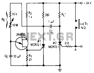
After one cycle of operation, SCR1 will be activated, resulting in a low voltage being applied to the UJT emitter circuit, which interrupts the tuning function. When pushbutton SI is pressed, or a positive pulse is applied at point...
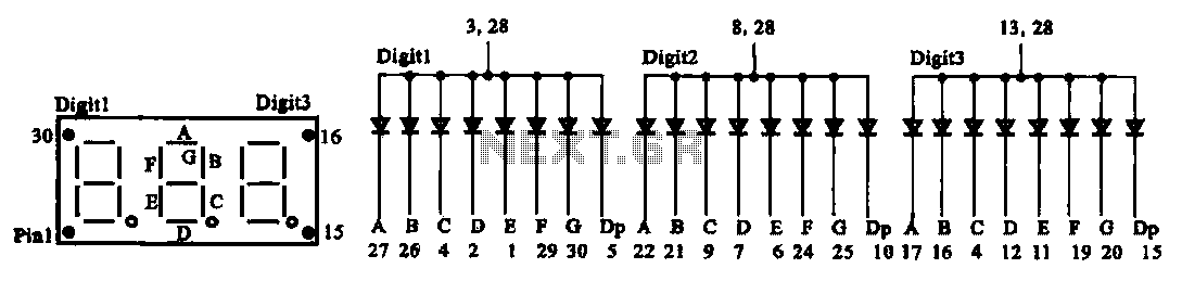
The document presents two types of digital display circuits. The first type (a) utilizes a common anode circuit configuration, while the second type (b) employs a common cathode circuit structure. The common anode display circuit configuration consists of multiple light-emitting...
This LED flasher circuit is a classic two-transistor flip-flop. It is a popular circuit often built by beginners in the electronics hobby. The schematic diagram of this well-known LED flasher circuit includes two transistors, two capacitors, four resistors, and...
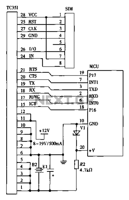
The design of a wireless data communication circuit is primarily intended for motor vehicles and fixed base station systems to facilitate close-range wireless data exchange. The circuit is based on the core chip nRF401 and its associated components. The...
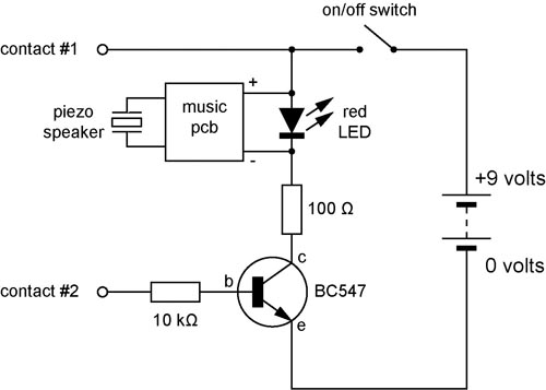
A continuity tester is useful for verifying that there is a conductive path between two points. This circuit offers the advantage of being highly sensitive, providing both visual and audible indications of continuity. An audible tester is particularly beneficial...
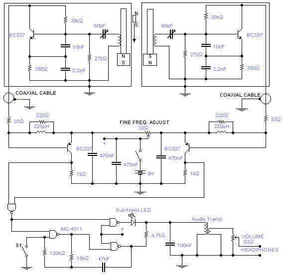
This is a rather sensitive circuit which will detect minute variations of a magnetic field, particularly the Earth magnetic field. The principle is based on an audio beat tone generated by two identical oscillators. These must be built in...