
Light control delay circuit 4
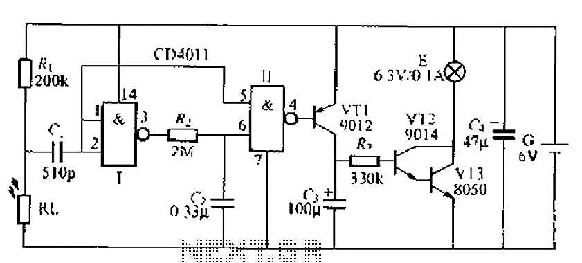
The core of the circuit utilizes a NAND gate configured as a monostable multivibrator, which typically remains in a stable state with a high output. Transistors VT1, VT2, and VT3 are kept in the OFF state, preventing the small lamp from lighting. In the event of a sudden power outage or when the main lights are turned off, the photosensitive resistor R1 experiences a spike in resistance, generating a pulse output that triggers the monostable multivibrator. This output pulse causes the transistors to conduct momentarily, allowing the small lamp to illuminate for a brief period.
The timing of the lamp's illumination is controlled by the components R1 and R2, which determine the duration for which VT1 conducts. This period is sufficient to charge the circuit, allowing VT2 and VT3 to conduct as well, thereby powering the small lamp. Once the charge dissipates, VT2 and VT3 will turn off, causing the small lamp to extinguish. If the ambient light is strong enough, the circuit will not activate, ensuring that the lamp remains off during well-lit conditions. Conversely, in dimming light conditions, R1 gradually increases in resistance, which can also prevent the lamp from lighting up.
The circuit may utilize a CD4011 integrated circuit for the NAND gates, with additional gates grounded if not in use. The design operates on a 6V supply, ideally powered by four 1.5V nickel-cadmium rechargeable batteries. The entire assembly is intended to be mounted within a lamp holder, which should be positioned to allow indoor light detection while avoiding direct exposure to the bulb to prevent optical feedback from interfering with the photosensitive resistor's function. Battery-powered light control delay lighting a small lamp, a sudden power outage or night to ask a blown fuse, the room was dark, it is difficult to find a match and candles: S ometimes after a late r turn off the lights to go to bed in the dark urine also had a sense of this small lamp, it o f the number of seconds moving lights, can give you cow tim will bring. The circuit characteristic only foot indoor light suddenly dimmed, small lamp to light, indoor light from dark if supported by the pregnancy or darken naturally slow, it will not light after a delay when laJ small lamp is off, the circuit does not Ran power consumption.
FIG LL, NAND gate I, integral composition punishment monostable nervous trigger, usually the circuit is in a stable state, and the output of NAND gate I high. VT1 -VT3 are in the OFF state, the small spider E does not shine. When the night suddenly stopped or electric lights, the photosensitive resistor RI. Suddenly high drought resistance, its upper output - Ar jump-sit pulse, purple (1 coupling, make towel-shot scraping turn into the transient, and not output low, VT conduction alone!.
when asked by a transient-shot R,. RJ decided instrument zero seconds to turn back to the steady-state child so VT1 conduction time is only seconds zero children, when asked this hatred sufficient to (. allow full charge, VT2, VT3 conduction along, after a small lamp E moisture electroluminescent .VT1 off, (j by R.
to VT2, VT3 composed of composite pipe discharge, small lights continue to glow until the (j discharged, VT2, VT3 cutoff recovery, small spider off. If the room light from dark and strong, Kl upper end of the negative pulse output, single-shot does not work, the lamp will not light E.
Similarly, if the light from light within channeling Ran Ran slowly becomes dark, RI slowly becomes a resistance large to thirty now hopping through C, coupling, single-shot status also will be a small change now small lamp still does not light up. and non rlI, may be one CD4.11 Ning IC number, the other two in the manifold/non-use and should be input as a gate grounded, and may not use floating .E 6.
3V, 0 1A small bulb .G preferably 4 section 5 nickel-cadmium rechargeable batteries. then the whole circuit is mounted within the lamp holder Wall RT. lampholder should extend a little outside experience allowed indoor light, but not direct exposure by the bulb E in order to avoid optical feedback.
Related Circuits
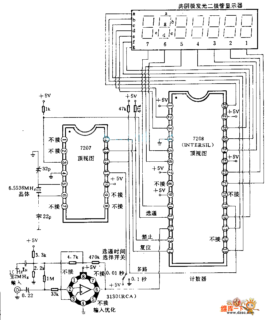
The 7208 seven-stage decimal counter can be utilized as a frequency counter. It features latch and multiplexing functions, along with direct digital driving circuitry and display driving circuitry. The output frequency of the 7207 IC 6.5536 MHz crystal oscillator...
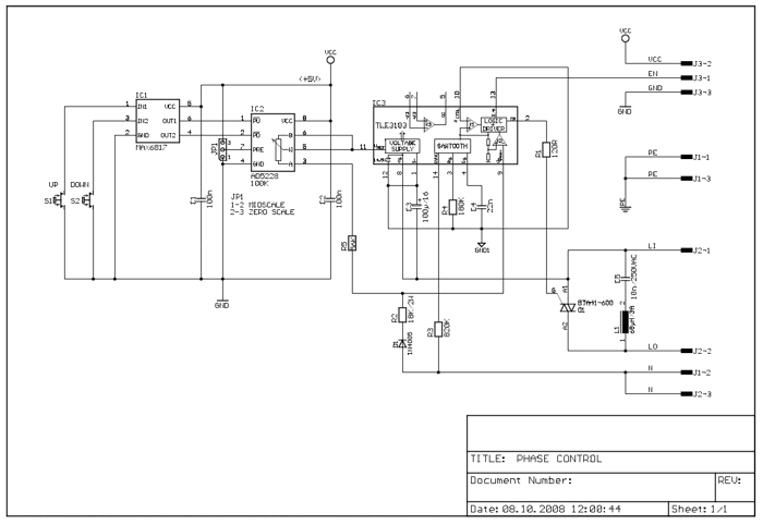
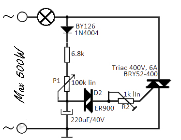
This circuit controls resistive and inductive loads up to 2,500W. Its primary component is the Siemens TLE3103 integrated phase control circuit, which includes its own power supply, a zero voltage crossing detector, and a logic driver. An additional feature...
A 5-minute circuit can continue to operate during a power outage, providing protection for the refrigerator. The refrigerator power protection circuit, designated as 1136, includes a power transformer that converts 220V voltage through a rectifier bridge (VD1). This setup...

The schematic includes programmable AVRs. For other members of the AVR family or additional programmable ICs compatible with Ponyprog, there is a J1 connector (CON10) that facilitates hardware expansion of the programmer. Additional information about compatible ICs can be...
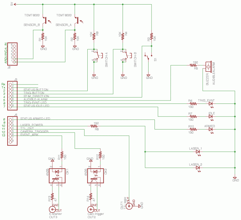
The core of the circuit features an Arduino microprocessor, represented by the header pins on the left side of the circuit schematic. Two analog inputs, labeled 0 and 1, are connected to the emitter sides of TEMT6000 ambient light...
This flashing light circuit utilizes triacs to produce an intermittent light with a variable frequency. Additional components include a diode (D1) and a semi-adjustable potentiometer (R2). The trigger capacitor (C1) is increased from 0.1 µF to 220 µF to...