
2500W Phase Control
This circuit is designed for controlling high-power resistive and inductive loads while ensuring safety and functionality through sophisticated components and configurations. The Siemens TLE3103 serves as the heart of the control mechanism, providing phase control capabilities essential for managing the load effectively. With its integrated power supply and zero voltage crossing detection, the TLE3103 minimizes electrical noise and enhances the reliability of the circuit.
The circuit’s operation is intuitively managed through a pair of pushbuttons, which adjust the output of the digital potentiometer, allowing for precise control over the load's power level. The debouncer IC (MAX6817) ensures that the pushbutton inputs are stable, eliminating the effects of mechanical bouncing that can lead to erratic behavior in digital circuits. The choice of the AD5228 digital potentiometer allows for a significant range of adjustment, with the potential for midscale or zero scale startup configurations depending on the jumper setting.
The use of the BTA41 triac, while rated for higher currents than necessary, provides an added layer of safety due to its isolated body, which is particularly advantageous when handling the circuit under load conditions. The snubber circuit, consisting of a 68 μH inductor, is critical for suppressing voltage spikes that can occur during the switching of inductive loads. The option to replace the inductor with a resistor offers flexibility in design, with the requirement to adjust the capacitor value accordingly to maintain circuit performance.
Overall, this circuit exemplifies a well-engineered solution for controlling high-power loads, integrating user-friendly controls and robust components to ensure both functionality and safety in operation.This circuit controls resistive and inductive loads up to 2, 500W. Its main functional device is an integrated phase control circuit - Siemens TLE3103. It contains its own power supply, a zero voltage crossing detector circuit and a logic driver. An additional feature is the low voltage input to enable/disable triac firing enabling/disabling the lo gic driver. The function is as follows: pin13 TLE3103 open (floating), trigger output active, tied to ground trigger output disabled. An UP and a DOWN pushbutton control a 32-step digital potentiometer (IC2, AD5228) via the debouncer IC1 (MAX6817).
The digital potentiometer has a power on reset pin which might be tied to ground causing the potentiometer to start at midscale, or to VCC causing it to start at zero scale. The desired function is selectable using jumper JP1. The triac (capable of driving 40A loads) is a bit overkill for the desired power but the BTA41 has an isolated body and therefore handling of the board under voltage is less dangerous as it is with phase on the package.
The snubber circuit uses a 68 H inductance but this might be replaced with a 100 resistor. When replacing the inductance C5 should have a value of 47nF. Remark: The debouncer circuit is manufactured with a SOT23-6 package. It might be soldered directly onto the board (DIP-6 package) using thin wires or an adapter board. 🔗 External reference
Related Circuits
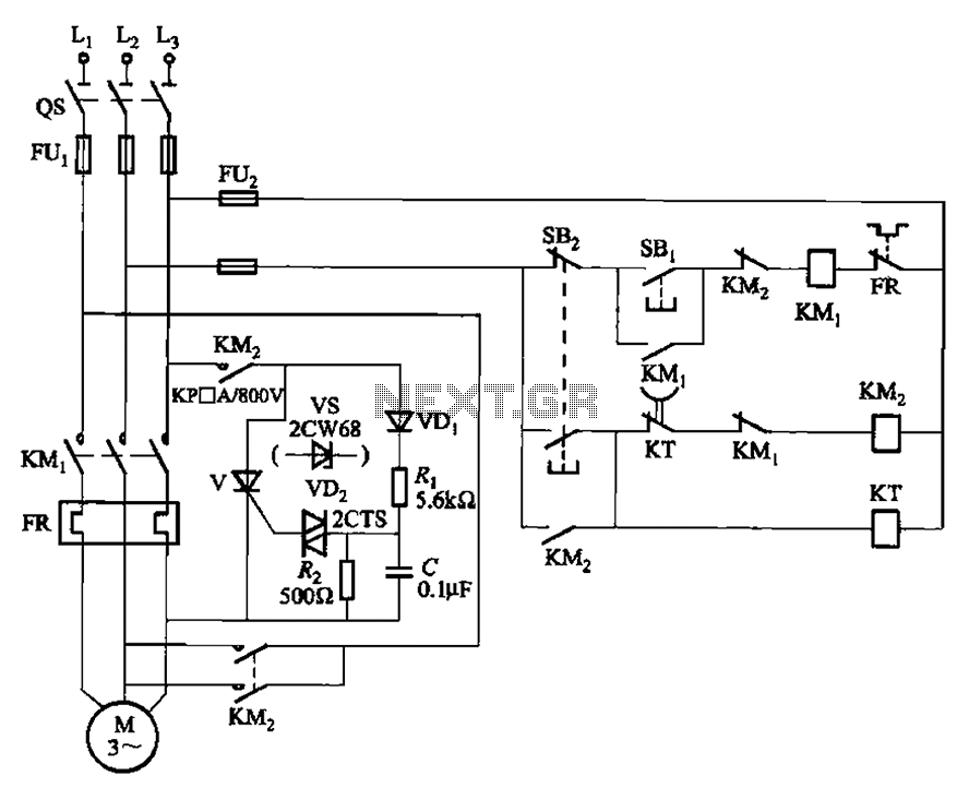
The circuit illustrated in Figure 3-148 eliminates the requirement for a step-down transformer by utilizing a thyristor for brake control in small capacity asynchronous motor braking applications. Upon shutdown, the contactor KM1 releases, while contactor KM2 engages the brake...
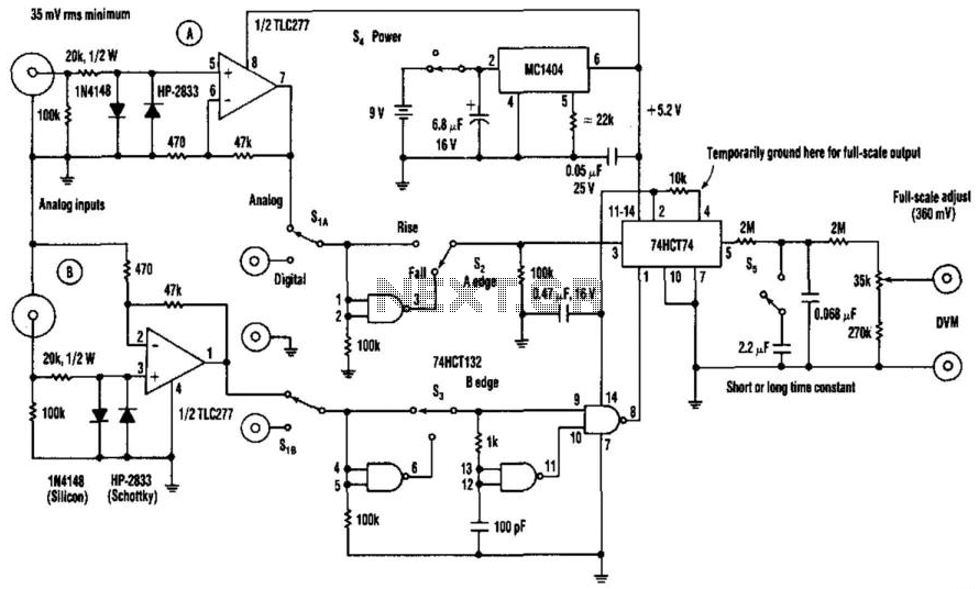
The phase-angle meter operates with both analog and digital inputs. A digital voltmeter (DVM) serves as the readout device. The output is 1 mV per degree, with a full-scale output of 360 mV corresponding to 360 degrees. The MC1404...
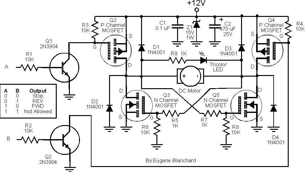
At 9 volts, the maximum stalled current of the motor types intended for use will be 700 mA. The selection of appropriate MOSFETs is crucial, particularly regarding their ratings for current and voltage handling. However, there are concerns about...
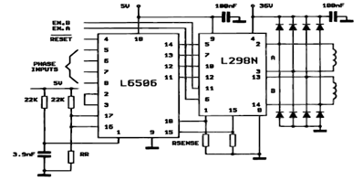
The following figure illustrates the control circuit for a two-phase bipolar stepper motor utilizing the current controller L6506. The L6506 integrated circuit generates the necessary signals to drive the inputs of the L298 bipolar stepper motor circuit driver. The circuit...
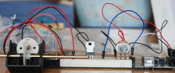
A quick circuit showing how to control the speed of a DC motor with a potentiometer with your Arduino board. Also shows how to use a TIP120 transistor to allow the Arduino control a larger power supply. This circuit utilizes...
The circuit utilizes two white LEDs, with the second LED connected across the emitter of the transistor and the negative ground. It requires its own limiting resistor in series, similar to R15 and D3 in the circuit diagram. If...
Warning: include(partials/cookie-banner.php): Failed to open stream: Permission denied in /var/www/html/nextgr/view-circuit.php on line 713
Warning: include(): Failed opening 'partials/cookie-banner.php' for inclusion (include_path='.:/usr/share/php') in /var/www/html/nextgr/view-circuit.php on line 713