
Refrigerator power protection circuit
The refrigerator power protection circuit 1136 is designed to ensure that the appliance remains operational during brief power interruptions, thereby preventing spoilage of contents within the refrigerator. The circuit employs a robust design that incorporates a transformer for voltage regulation, a rectifier bridge for converting AC to DC, and various components such as capacitors, resistors, transistors, and thyristors to manage the charging and discharging cycles effectively.
The operation begins with the transformer stepping down the 220V AC supply, which is then rectified by the bridge to provide a stable DC voltage. The control circuit is crucial for detecting the power state and managing the relay and thyristor operations. The system intelligently utilizes the charge and discharge characteristics of capacitors to create a delay mechanism, ensuring that the refrigerator does not restart immediately after power restoration, which could lead to further electrical surges.
The integration of a thyristor and relay in the circuit allows for precise control over the refrigerator's operation, while the inclusion of protective components like Zener diodes and bidirectional thyristors safeguards the sensitive electronic components from voltage spikes or surges. Moreover, the adjustable timing feature provides flexibility in operation, accommodating various refrigerator models and user preferences.
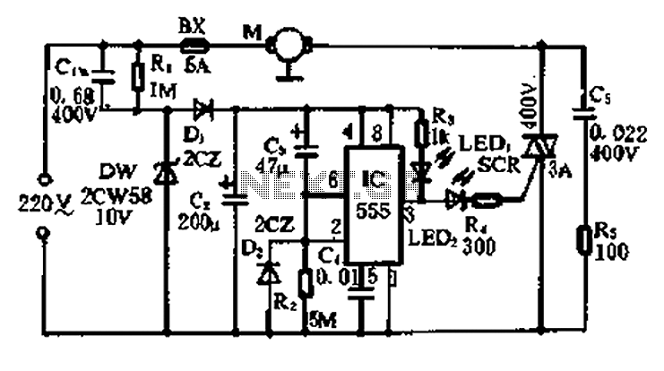
In conclusion, the refrigerator power protection circuit 1136 is a well-engineered solution that combines multiple electronic components to ensure reliable operation during power outages, thereby enhancing the longevity and efficiency of refrigeration systems.5 min circuit can continue to operate in the state of the power outage, the role to protect the refrigerator. Refrigerator power protection circuit 1136 as shown in FIG. T for the power transformer, 220V voltage by the rectifier bridge VD1 ~ fM Ct charge of power supply voltage control circuit + 1ZV, for the first time. Since there is no charge on the G, VT2 off, A point of high potential., VT3 deadline, TRIAC VTHZ due VD7 triggered by conduction, the load is energized, Refrigerator start work.
At the same time, R2 to c2 charged and the B point potential rise by R, VTH1 triggered thyristor conduction. Relay K pull its normally open contact K is closed; the G diode VD5 charging voltage of + 12y, the circuit is in standby power protection.
Once the power circuit, the relay K energized. Normally open contacts K release, since the c: 1 charged with a charge voltage of + 12V, is applied to the gate of VT2 pole. Because the pole, no current links between the gate and source-drain. Therefore, the charge on C3 remains substantially unchanged. C3 on the voltage applied to the VT2 between the gate-source, so that VGS is greater than the threshold voltage VT2 U, so that the drain and source of the field effect transistor conductive channel between a certain way, although there is no power supply voltage, but the drain between panels D and the source S, equivalent to a closed switch state.
During this time, if the power to call, VT2 place in the conduction state, the A point at a low potential, HL lights that delay protection. Transistor VT3 conduction, C point at a high potential, the diode VD7 off, triac trigger current VTH2 be less than the cut-off, the refrigerator does not work.
during this time. The R6 always sampled voltage of the transistor f ] turned, B point is low, does not trigger the thyristor VTH1, following appliances K does not pull, the normally open contacts K is not action, maintaining A point low. A point of time to maintain low potential may be adjusted to control the wind. With C3 for acupuncture discharge. Reducing the charge on G, the field effect transistor VT2 drain, source current is gradually reduced, sampling voltage reduction on R less, eventually leading to VT1 end, B point potential rise, triggering VTH1 turn, relay K energized, normally open contact.
K is closed,. VTZ Wei stop. A point to a high potential, C point into low, diode VD7 trigger, VTH2 conduction, refrigerator electrical work. Zener granted tube vs. For protecting the field effect transistor VT2 past, Rg, C4 in series and in parallel i VS2 protection bidirectional thyristor has VTHZ, Shu, HL indication of the delay circuit.
Related Circuits

The circuit activates a light corresponding to the first button pressed in a "Who's First" game. Three stages are illustrated, but the circuit can be expanded to accommodate any number of buttons and lamps. The described circuit operates as a...
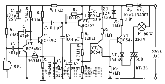
The circuit utilizes condenser microphones to detect sound and convert it into signal variations. This signal is then processed through directly coupled transistors VT1 and VT2, which form an amplification stage before being fed into a switching circuit. The...
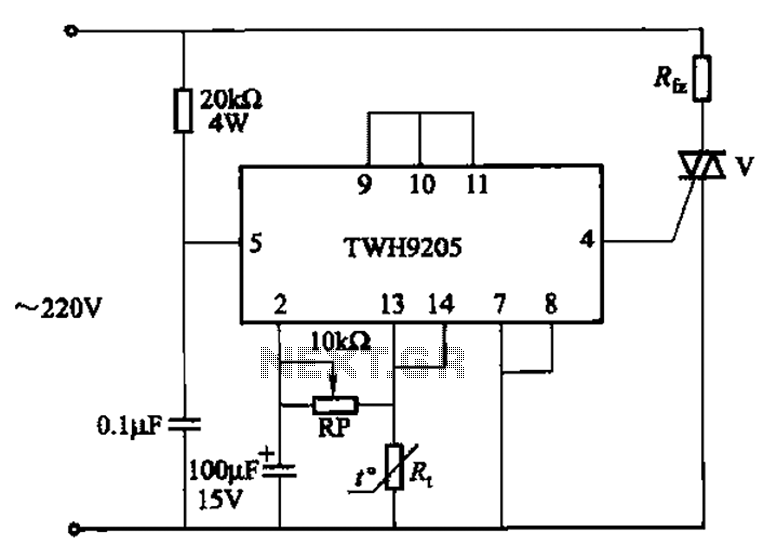
This circuit is used for temperature control in various heating equipment such as water heaters, microwave ovens, air conditioners, refrigerators, fans, and automatic fire extinguishing devices. It includes a negative temperature coefficient (NTC) thermistor as the temperature sensing element...
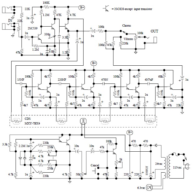
The Univibe is a footpedal-operated phaser or phase shifter designed to generate chorus and vibrato simulations for electric organs or guitars. It was introduced in the 1960s by Shin-ei, with the intention of emulating the "Doppler sound" characteristic of...
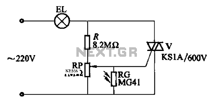
An automatic light control circuit is designed to illuminate a lamp when it is dark and to turn off the light at daybreak. The circuit, as shown in Figure 2-86, employs bidirectional thyristor tubes and features a straightforward design....
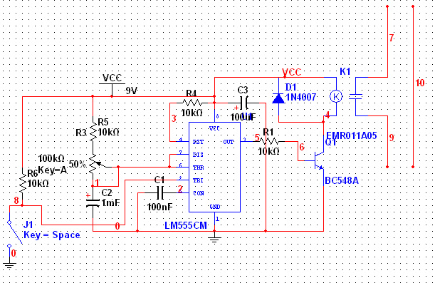
The 555 Timer has extensive applications in electronics. This document describes the use of the 555 Timer in a monostable multivibrator configuration to trigger a transistor driver that energizes a relay, which in turn operates a 230V AC lamp...
Warning: include(partials/cookie-banner.php): Failed to open stream: Permission denied in /var/www/html/nextgr/view-circuit.php on line 713
Warning: include(): Failed opening 'partials/cookie-banner.php' for inclusion (include_path='.:/usr/share/php') in /var/www/html/nextgr/view-circuit.php on line 713