
Light/Dark Switch With Relay
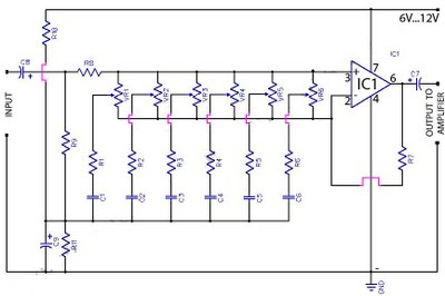
The described circuit utilizes a light-dependent resistor (LDR) to detect light levels and control a relay. The LDR, which exhibits high resistance in dark conditions, maintains a low signal at pin 2 of the circuit. This low signal state indicates that there is insufficient light present. As ambient light increases, the resistance of the LDR decreases significantly, often to a few hundred ohms, resulting in a high signal at pin 2.
This change in state at pin 2 is crucial as it triggers the base of transistor Q1 via pin 6 and resistor R4. The transistor Q1 operates as a switch, allowing current to flow from the collector to the emitter when it is biased on. As Q1 turns on, it activates the relay, which can be used to control a high-power load, such as a light or an alarm, based on the ambient light conditions.
The circuit may also include additional components such as a diode across the relay coil to prevent back EMF from damaging the transistor when the relay is de-energized. The relay serves as an interface between the low-power control circuit and the high-power device, making it suitable for various applications including automatic lighting systems or security alarms that respond to changes in lighting conditions.
The inclusion of a light/dark switch allows for manual adjustment of the sensitivity or operational mode of the circuit, providing flexibility in its application. This circuit is an effective solution for environments where light detection is required to automate other electronic systems.The circuit as shown act as a light detector. Under normal conditions the resistance of the LDR is high, keeping pin 2 low. When light falls onto the LDR the resistance drops to a couple hundred ohms and triggers pin 2 high which biases the base of Q1 via pin 6 and R4 and in turn activates the relay. Light/Dark switch Circuit with relayAs. 🔗 External reference
Related Circuits
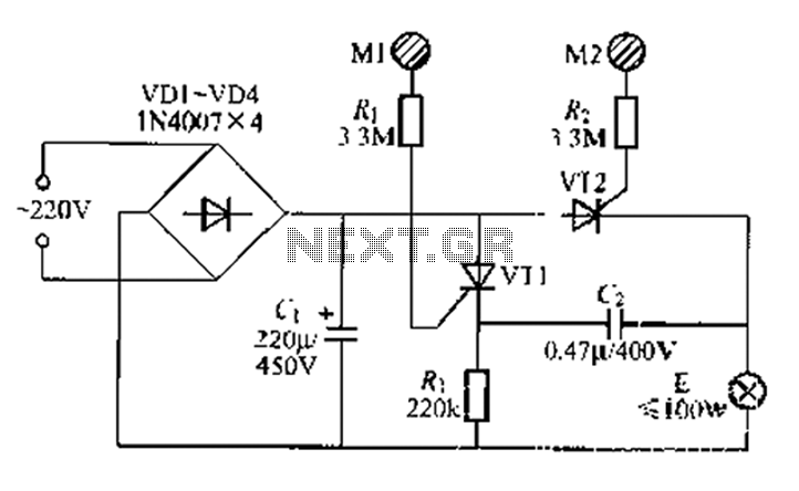
A circuit configuration features a relatively new strong key touch-state switch. Normally, the thyristors VT1 and VT2 are in the off-state, allowing minimal current to pass through the lamp F. At this point, the capacitance C comes into play....
Our circuit is amplifying the current flowing through your finger (when it touches the touch plate) 10,000 times and this is sufficient to illuminate the LED. The current flowing through your finger (when touching the touch plate) is only...
Using high-beam headlights while driving on the highway can significantly enhance visibility; however, they may pose a blinding risk to other drivers. This straightforward circuit can be integrated into the headlight switch to enable automatic switching between high and...
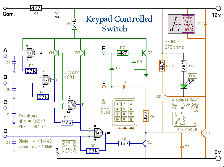
This is a universal version of the four-digit alarm control keypad. The design has been modified to free up the relay contacts, allowing the circuit to function as a general-purpose switch. A single pole changeover (SPCO) or single pole...
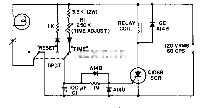
This simple timing circuit can delay an output switching function from 1 second to about 1 minute. The SCR is triggered by only a few microamps from the timing network R1-C1 to energize the output relay. The timing circuit described...
Configured with capacitive coupling by inserting a small capacitor between the phototransistor and the bipolar transistor, this relay circuit will respond only to rapid changes. This relay circuit utilizes capacitive coupling to enhance its responsiveness to fast signal changes. The...