
Press light switch double circuit 9

This circuit configuration employs a touch-sensitive switch mechanism that utilizes thyristors for efficient control of a lamp. The design begins with the integration of two thyristors, VT1 and VT2, which are crucial for switching the lamp on and off based on touch input. In the default state, both thyristors remain off, resulting in minimal current flow through the lamp F, which is kept in a dim state.
The bridge rectifier, composed of diodes VD1 through VD4, is responsible for converting the AC voltage into a stable DC voltage of approximately 310V. This high voltage is essential for the operation of the thyristors, which require a sufficient forward voltage to conduct.
The operation is initiated when a user touches the electrode sheet M2, which allows a small leakage current from the optional human foot Z to pass through the gate of VT2. This current effectively turns on VT2, which subsequently powers the lamp E. The design ensures that even if the trigger current is removed, VT2 remains in the on state due to the feedback mechanism provided by the left-hand rear electrode films, which act as a trigger for VT2.
When the user removes their foot, the capacitance Cz discharges, causing VT2 to turn off. The resistor R plays a critical role in balancing the charge distribution across the circuit, allowing for smooth operation and preventing unintended triggering of the thyristors.
To turn off the lamp, the user can simply touch the electrode sheet M1, which triggers VT1. This action allows the stored charge to flow through both VT1 and VT2, leading to a rapid loss of forward voltage across VT2 and consequently turning off the lamp E. This feature of the circuit highlights its energy efficiency, as the design allows the lamp to be turned off with minimal current flowing through VT1.
The choice of thyristors such as the 2N6560 or BT169D ensures that the components can handle the necessary current and voltage ratings, while maintaining a compact form factor. The overall design is optimized for reliability and ease of use, making it suitable for various applications where touch-sensitive control is desired.A circuit configuration is relatively new strong key touch-state switch. Normally, product thyristor VT1, VT2 are in the off-state I-what little light the lamp F. At this point capacitance c. After VD1 ~ VD4 bridge rectifier, charging about full around 3lOV DC voltage. Turn on the lights, just click the touch electrode sheet M2, the leakage current of the Optional human foot z passing through the gate of VT2, VT2 so quickly opened, the lamp E powered light. Left hand rear electrode films, Ding Tian thyristor as in Afghanistan back into the road, although the loss of r door trigger current, but still maintain VT2 Ji state.
(Ix) cut off the feet, electric capacitance Cz unravel VT2, R, can be filled with left and right positive negative charge. Turn off the lights when needed, touch an F electrode sheet Ml, empathy thyristor VT1 can quickly open, then (,: through the stored charge through VT1 VT2 superimposed on the reverse side Sh make VT2 Gang instant loss forward anode voltage shutdown, power off the lamp E wood Road brother lU feature is that as long as the sample a suitable value of R after the lamp when trampling manpower from Ji after M1, the anode current J flowing through the VT1 little can wri themselves off to save power circuit consumption .VTI, VT2 u J selected 2N6560, BT169D type and other small plastic unidirectional Transistor, other components requires Sapporo FIG.
Related Circuits
A user has been experimenting with modifications to a budget-friendly MXL V67s microphone to enhance its performance, specifically aiming to improve the condenser quality until a higher-end model can be acquired. The MXL V67s is a popular choice among budget-conscious...

This low-voltage, high-current output switching power supply operates from a 220-V AC input. The circuit employs an ST2 diac relaxation oscillator, Q3, C1, and the diac to initiate conduction of the output switching transistor Q1. The on-time of Q1...
Thank you for your responses to my previous thread. I appreciate it. Please advise on how to convert a 24V DC and what circuit diagram should be used. To convert a 24V DC supply to a different voltage level, several...

This module, available in a Stainless DIL 8 configuration, can independently measure four analog voltages ranging from 0 to 5 volts and transmit the results as four characters over a standard asynchronous serial link. Its serial output is compatible...
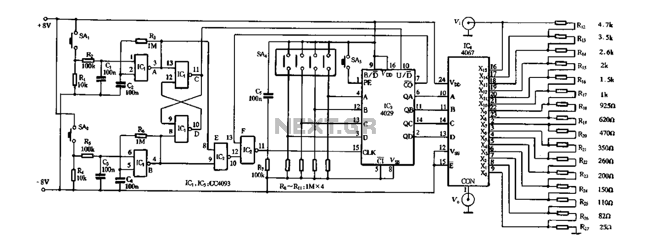
Figure 4-14 illustrates a digital integrated circuit featuring 16 preset potentiometers for Siniperca electronic circuits. The circuit comprises three main components: an input controller, a presettable counter, an analog electronic switch, and a resistor network. It includes a push-button...

This solar light bulb is designed to assist individuals residing in villages by offering an affordable alternative to harmful kerosene lamps. It aims to empower impoverished communities by replacing kerosene with clean, solar-powered lighting. The core component of this...
Warning: include(partials/cookie-banner.php): Failed to open stream: Permission denied in /var/www/html/nextgr/view-circuit.php on line 713
Warning: include(): Failed opening 'partials/cookie-banner.php' for inclusion (include_path='.:/usr/share/php') in /var/www/html/nextgr/view-circuit.php on line 713