
Time-delayed relay
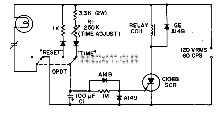
The timing circuit described employs a silicon-controlled rectifier (SCR) as the primary switching element, utilizing a resistor-capacitor (R-C) timing network to establish the desired delay. The timing network consists of resistor R1 and capacitor C1, which work together to create a time constant that governs the delay before the output relay is activated.
Upon powering the circuit, capacitor C1 begins to charge through resistor R1. The time it takes for the capacitor to charge to a specific voltage level, typically the gate trigger voltage of the SCR, determines the duration of the delay. The relationship between the resistance (R1), capacitance (C1), and the voltage across the capacitor can be described by the formula:
\[ t = R1 \times C1 \times \ln\left(\frac{V_{supply}}{V_{supply} - V_{trigger}}\right) \]
where \( t \) is the time delay, \( V_{supply} \) is the supply voltage, and \( V_{trigger} \) is the gate trigger voltage of the SCR.
Once the voltage across C1 reaches the gate trigger threshold of the SCR, the SCR conducts, allowing current to flow through the output relay coil. This energizes the relay, closing its contacts and activating the connected load. The SCR remains in the conducting state until the current through it falls below a certain holding current threshold, at which point it turns off. This characteristic allows for the relay to remain activated for as long as the input power is maintained.
The circuit's design ensures that only a minimal amount of current, measured in microamps, is required to trigger the SCR, which makes it efficient and suitable for applications where low power consumption is critical. Overall, this timing circuit is ideal for applications requiring precise control of output timing, such as in automation systems, delay timers, or sequential control processes.This simple timing circuit can delay an output switching function from 1 seconds to about 1 minute The SCR is triggered by only a few microamps from the timing network Rl-Cl to energize the output relay. 🔗 External reference
Related Circuits
Configured with capacitive coupling by inserting a small capacitor between the phototransistor and the bipolar transistor, this relay circuit will respond only to rapid changes. This relay circuit utilizes capacitive coupling to enhance its responsiveness to fast signal changes. The...
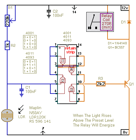
The first circuit energizes the relay when the light rises above the preset level. The second circuit energizes the relay when the light falls below the preset level. The two circuits are practically identical. The only difference between them...
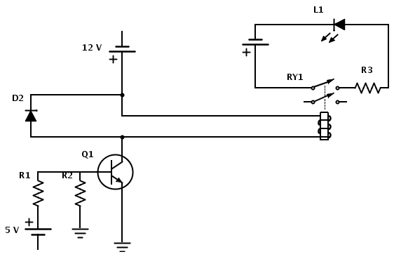
Create a circuit that enables the activation of a relay to control an LED. The relay operates at 12 V, while the available input voltage is 5 V. An NPN transistor will be utilized to switch the power to...
This circuit provides a straightforward and efficient method for interfacing two relays in switching applications. The relay driver utilizes a standard BC547 NPN transistor (or equivalent) to enhance the input impedance. It is a widely used driver capable of...
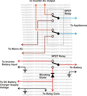
This inquiry has been presented multiple times on this blog regarding the implementation of a changeover selector switch for the automatic toggling of an inverter when AC mains power is available, and vice versa. The system must also enable...
The circuit requires a double pole, double throw relay in conjunction with a single transistor to allow toggling the relay with a momentary push button. One set of relay contacts is used to control the load, while the other...