
Light detector switch

To create a circuit that automatically turns on an LED in low-light conditions while minimizing battery drain, a more efficient design can be implemented using a photoresistor (LDR), a transistor, and a few passive components. The circuit can be simplified by replacing the relay with a transistor, which will act as a low-power switch.
The circuit design begins with the photoresistor, which changes its resistance based on the ambient light level. In bright conditions, the resistance of the LDR is low, preventing current from flowing to the base of the transistor, thus keeping the LED off. As the light level decreases, the resistance of the LDR increases, allowing a small current to flow through a voltage divider formed by the LDR and a fixed resistor. This current will be sufficient to turn on the transistor.
A common NPN transistor, such as the 2N3904, can be used for this application. The base of the transistor is connected to the junction of the LDR and the fixed resistor, while the emitter is connected to ground. The collector of the transistor is connected to the LED, which is in turn connected to the positive terminal of the battery. A current-limiting resistor should be placed in series with the LED to prevent excessive current from damaging it.
To ensure that the circuit operates efficiently and does not drain the batteries unnecessarily, a low-power transistor should be chosen, and the values of the resistors should be calculated to provide just enough base current to switch the transistor into saturation when the light level falls below a certain threshold. Additionally, a capacitor can be added in parallel with the LED to smoothen the current and provide a slight delay in turning off the LED when the light returns.
This design not only achieves the desired functionality of turning on the LED in darkness but also conserves battery life, making it suitable for applications powered by two AA batteries. Further optimization can be performed by adjusting the resistor values and selecting components that minimize power consumption while maintaining reliable operation.Anyone know how I could make an led come on when it gets dark automatically?I made a version with a relay and photoresistor that worked but then I was think won`t that drain the battery to much?I`m trying to use this in conjunction with a circuit I got from here like the Brinkmann and it uses only 2 aa batteries. I found some info on the web talking about using a transistor as an on and off switch but my only electronic experience is what I have learned from Mr.Als course.So it`s still..
🔗 External reference
Related Circuits
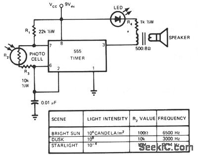
This circuit's frequency of oscillation increases directly with light intensity. The greater the light intensity, the higher the frequency of the oscillator. The 555 timer operates in astable oscillator mode, where frequency and duty cycle are controlled by two...
The DTMF codec stands for dual-tone multi-frequency codec. The multiple-channel infrared remote control switch circuit that incorporates the DTMF is depicted in the figure. It consists of an infrared remote control signal emitter, an infrared receiving signal amplifier, a...
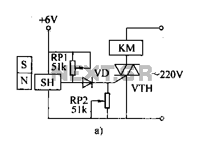
The automatic weapon features a magnetic switch circuit that is simple, reliable, has a low failure rate, and offers good versatility. It can be used for output performance or converted into mechanical displacement applications. The circuit diagram utilizes a...
The optical safety switch circuit includes a power supply circuit, a light control circuit, and a control implementation circuit (switch circuit). The power circuit is made up of a power transformer (T), a bridge rectifier (UR), and a filter...

Public Lab is an open community that collaboratively develops accessible, open-source, Do-It-Yourself technologies for investigating local environmental health and justice issues. Public Lab focuses on creating tools that empower individuals and communities to engage in environmental monitoring and advocacy. These...
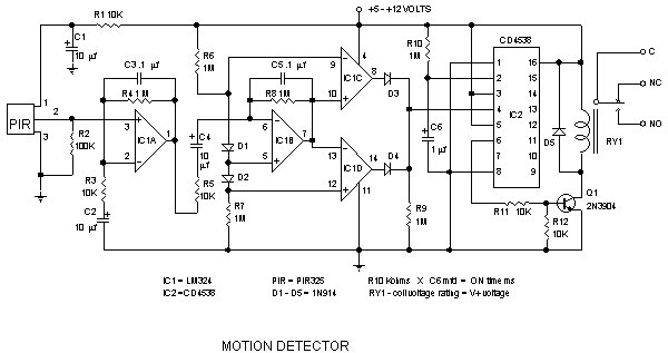
Detector components and infrared motion work, electronic circuit schematic wiring diagram, detector components and infrared motion work. The electronic circuit schematic for an infrared motion detector typically consists of several key components that work together to detect motion through infrared...