
Optical safety switch circuit diagram

The optical safety switch circuit is designed to enhance safety in electronic systems by utilizing light-sensitive components to control the operation of a relay. The configuration begins with the power supply circuit, which plays a critical role in converting the high-voltage AC input (220V) into a usable low-voltage DC output (6V). The transformer (T) steps down the voltage, while the bridge rectifier (UR) converts the AC voltage into DC. The filter capacitor (C2) smooths the rectified output, ensuring a stable DC voltage supply.
In the light control circuit, the photosensitive resistor (RL) detects ambient light levels, adjusting the circuit's response based on light intensity. The resistors (R1 to R3) and the potentiometer (RP) form a voltage divider network that calibrates the sensitivity of the light detection. The transistor (V1) acts as a switch, controlling the flow of current based on the voltage received from the light control circuit. The capacitor (C1) may be used for stability and filtering purposes, further refining the control signal.
The control implementation circuit is responsible for executing the action based on the control signal. Diodes (VD1 and VD2) are used to protect the circuit from back EMF generated by the relay (K) during operation. Transistors (V2 and V3) amplify the control signal to drive the relay, which can connect or disconnect a load based on the light conditions detected by the light control circuit.
Overall, this optical safety switch circuit is a robust solution for applications requiring automatic control based on light levels, enhancing operational safety and efficiency in various electronic devices.The optical safety switch circuit consists of the power supply circuit, light control circuit and control implementation circuit (switch circuit), the circuit is shown as the chart. Power circuit is composed of the power transformer T, bridge rectifier UR and filter capacitor C2. Light control circuit is composed of the photosensitive resistor RL, resistors R1 ~ R3, potentiometer RP, transistor V1 and capacitor C1. Control implementation circuit consists of the diodes VD1 and VD2, transistors V2 and V3 and the relay K. AC 220Y voltage bucked by T, filtered by UR and rectified by C2 can provide 6V DC voltage for light control circuit and control implementation circuit.
R1 ~ R3 use potentiometer l/4W carbon or metal film resistors. RP selects variable potentiometer or solid film variable resistor. 🔗 External reference
Related Circuits
The chart illustrates a clock designed for a competition, utilizing a 555 timer circuit. This circuit is characterized by its novel design, reliable performance, ease of assembly, and engaging functionality. The 555 timer is available in two types: bipolar...
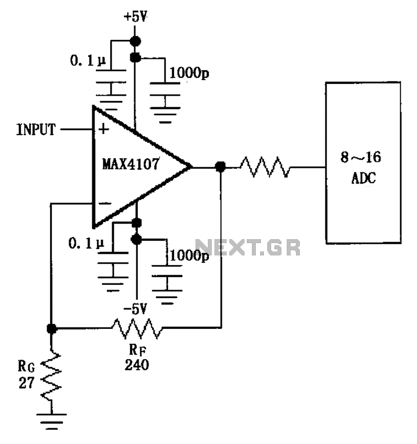
The inverting gain circuit utilizing the MAX4107 is configured as an ADC input buffer. The gain of the amplifier is established by the ratio of resistors RF and RG, which set the gain figure to approximately 10. The inverting gain...
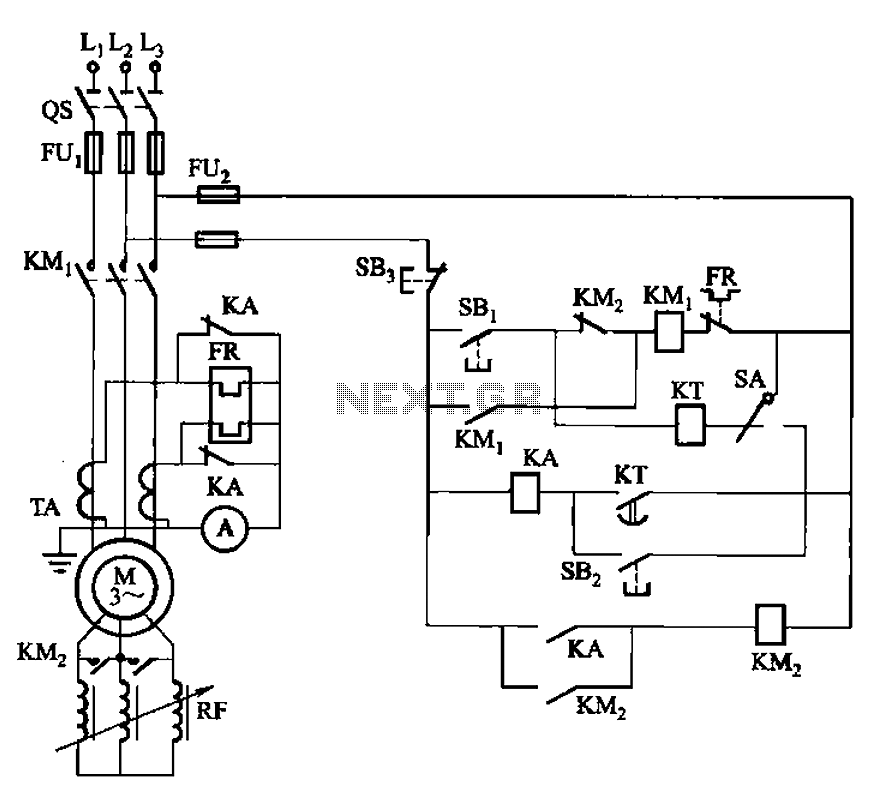
The circuit shown in Figure 3-164 can operate in both manual and automatic modes. During startup, the normally closed contact of relay KA is shorted, which affects the heating element to avoid prolonged startup times that could lead to...

The circuit utilizes the Trigger and Threshold pins (2 and 6) to monitor maximum and minimum voltage levels. Two voltage comparator operational amplifiers within the 555 timer manage the output state, switching it on or off. The Trigger pin...
This project uses the 1.2v rechargeable battery and solar panel from a Solar Garden Light. These lights can be bought for less than $5.00 in most $2.00 shops or similar shops that sell general household items. We are also...
This article presents a high reliability 1200V High Voltage Integrated Circuit (1200V HVIC) for half bridge driver applications, aimed at reducing the IC's supply current by approximately 50%. The 1200V High Voltage Integrated Circuit (HVIC) is designed specifically for half-bridge...