
Detector Components & Infrared Motion Work
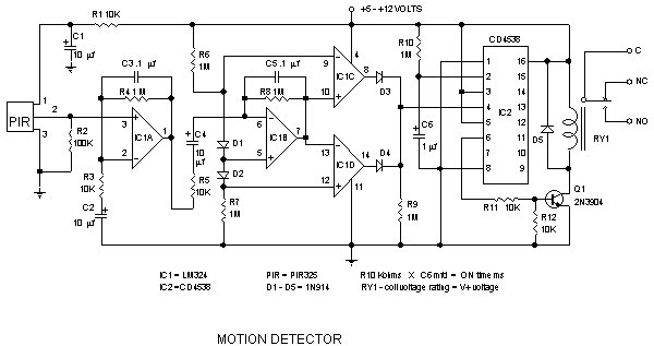
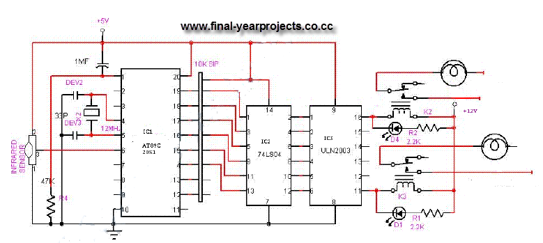
The electronic circuit schematic for an infrared motion detector typically consists of several key components that work together to detect motion through infrared radiation. The primary elements include an infrared (IR) sensor, a microcontroller or comparator circuit, a power supply, and output devices such as alarms or lights.
The IR sensor is the heart of the motion detection system. It detects infrared radiation emitted by objects, particularly warm bodies like humans or animals. The sensor generates a voltage signal when it detects a change in infrared levels, indicating motion within its field of view.
This signal is then fed into a microcontroller or comparator circuit, which processes the input from the IR sensor. The microcontroller can be programmed to differentiate between normal environmental changes and actual motion. It can also be configured to adjust sensitivity levels, set time delays for the output activation, and manage other parameters for optimal performance.
The power supply provides the necessary voltage and current to the entire circuit, ensuring that all components operate effectively. Typically, a battery or a regulated power source is used, depending on the application and location of the motion detector.
Output devices, such as LEDs, buzzers, or relays, are connected to the microcontroller. When motion is detected, the microcontroller activates the output device to signal the presence of motion. This may involve lighting up an LED, sounding an alarm, or triggering a camera or other security devices.
The wiring diagram for such a circuit would illustrate the connections between the IR sensor, the processing unit, the power supply, and the output devices. Proper attention to component specifications and circuit layout is crucial to ensure reliable operation and minimize false triggers. The schematic should also include any necessary resistors, capacitors, and other passive components required for signal conditioning and stabilization.Detector Components & Infrared Motion Work, Electronic Circuit Schematic Wiring Diagram, Detector Components & Infrared Motion Work. 🔗 External reference
Related Circuits
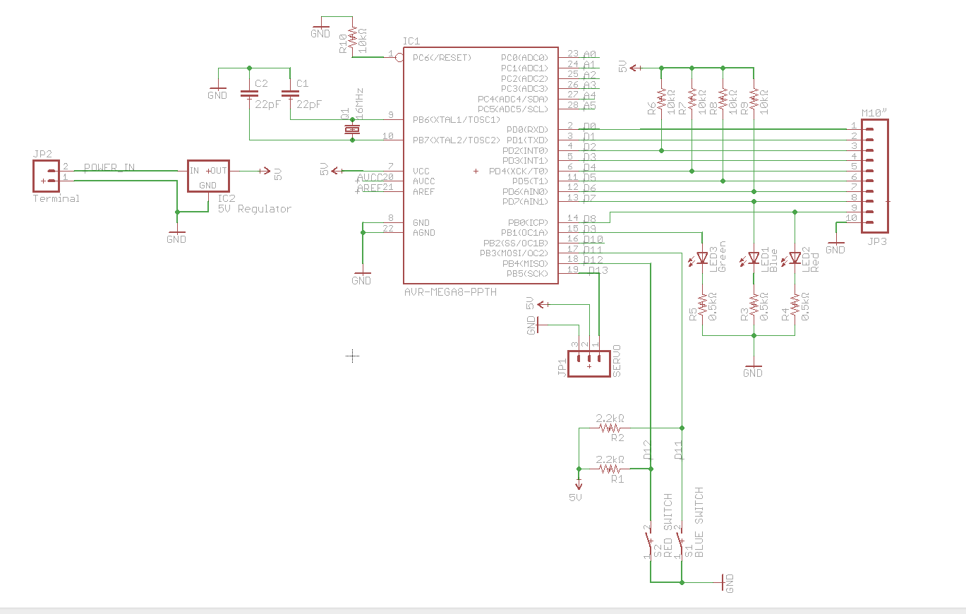
A circuit utilizes a keypad, a servo, and several LEDs, connected to an Arduino Uno. The objective was to integrate all components onto a single PCB, effectively creating a custom version of the Arduino. Upon startup, the red LED...

This figure illustrates a block diagram of modern automated systems that incorporate closed-loop feedback for motion control. These systems typically feature a servo system consisting of feedback elements and a motor driver, which work together to provide accurate and...
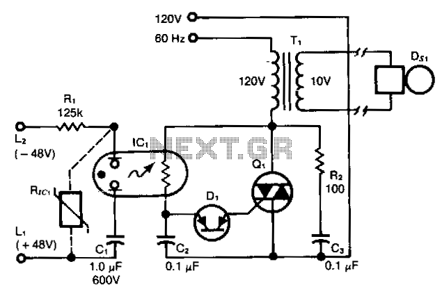
This ring detector, utilizing a neon-LDR (light-dependent resistor) optocoupler, simplifies interfacing with telephone lines. The ring detector circuit is designed to detect the ringing signal from telephone lines, which typically operates at a frequency of 20 Hz to 25 Hz...
This circuit gives out an alarm when its sensor is wetted by water. A 555 astable multivibrator is used here which gives a tone of about 1kHz upon detecting water. The sensor when wetted by water completes the circuit...
This is a comprehensive electrical project report on an Infrared Remote Control On/Off Switch, submitted to fulfill the requirements for the Bachelor of Engineering degree in Electrical Engineering. The project is designed to control the operation of home appliances...

The circuit can be used to determine whether an input signal falls within a specific frequency range. The device comprises three integrated circuits (ICs), including a dual monostable multivibrator and two dual D-type flip-flops. The signal whose frequency is...