
Light dimmer circuit using DIAC and TRIAC

The light dimmer circuit employs a TRIAC (Triode for Alternating Current) as the primary switching device, which allows for control of AC power to the lamp. The DIAC (Diode for Alternating Current) serves as a triggering element that enables the TRIAC to turn on when the voltage across it exceeds a certain threshold, known as the breakover voltage.
In this configuration, the resistor and capacitor form an RC timing circuit. The resistor, valued at 500K ohms, limits the current flowing into the capacitor, controlling its charge time. The variable resistor, often referred to as a potentiometer, allows for fine-tuning of the resistance value, thereby adjusting the time it takes for the capacitor to charge to the DIAC's breakover voltage.
When the capacitor reaches the breakover voltage, the DIAC transitions from a non-conducting to a conducting state, effectively providing a pulse to the gate of the TRIAC. This pulse triggers the TRIAC, allowing current to flow through the lamp, thus illuminating it. The phase angle at which the TRIAC is triggered determines the brightness of the lamp; a later trigger results in a dimmer light output.
The circuit can be designed to operate with various types of lamps, including incandescent and some types of LED lamps, depending on the specifications of the TRIAC and DIAC used. Proper selection of these components is crucial for ensuring reliable operation and achieving the desired dimming effect. Additionally, incorporating snubber circuits may be necessary to protect the TRIAC from voltage spikes that could occur during operation, especially with inductive loads.
Overall, the described light dimmer circuit provides an effective means of controlling light intensity through simple components and straightforward design principles.Light dimmer circuit is using to adjust the illumination of lamp. The below circuit shows the basic TRIAC triggering circuit using DIAC. Here in this circuit the light illumination is controlled using TRIAC and DIAC. The resister and capacitor are connected in series. The capacitor is made to charge through the 500K resistor. When the capacitor st arts charging and when it reaches above the breakover voltage of DIAC, it starts conducting. Hence capacitor voltage is applied to TRIAC gate and it turns-on. The charging of the capacitor can be controlled by the variable resistor. Which indirectly controls the firing delay of TRIAC. 🔗 External reference
Related Circuits
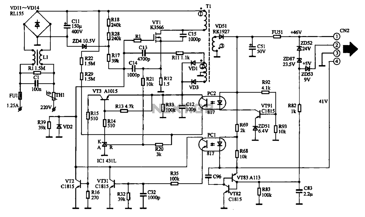
The EPSON PHOTO 830U printer power circuit illustrates the power supply circuit for the EPSON PHOTO 830U printer, which operates as a switching power supply. During normal operation, the power supply input socket receives a 220V AC supply to...
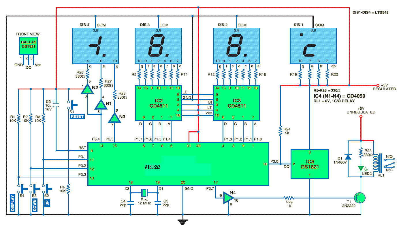
This standalone digital thermometer regulates the temperature of a device based on its requirements. It displays the temperature on four 7-segment displays, with a range from 55 to +125 °C. The core of the circuit is the AT89S52 microcontroller,...
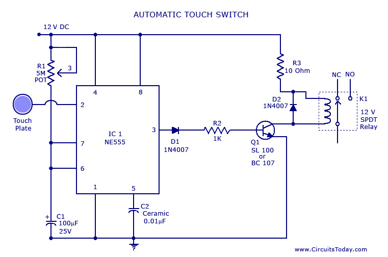
A touch switch circuit schematic utilizing a 555 integrated circuit (IC). When the touch plate is activated, a relay is switched ON for a predetermined duration, which can also be adjusted. The touch switch circuit employs a 555 timer IC...
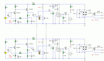
This is an intercom circuit that utilizes the LM380 as the audio amplifier and two transistors for the microphone preamplifier. The sound quality is sufficiently good while maintaining a low construction cost. The circuit comprises two identical intercom units,...
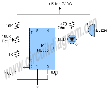
This schematic illustrates a beeper circuit designed to produce a continuous beep sound while simultaneously flashing an LED. The beeper circuit typically consists of a few key components: a sound-generating device (such as a piezo buzzer), an LED for visual...
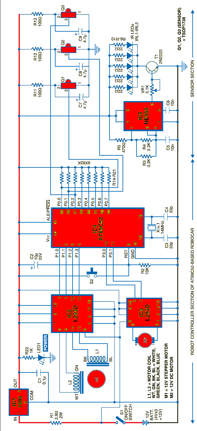
A robot can be defined as an electro-mechanical system with the capability of sensing its environment, manipulating it, and acting according to a preprogrammed sequence. It is a machine that... Robots are complex systems that integrate various components to perform tasks...