
beeper circuit

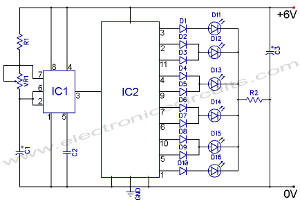
The beeper circuit typically consists of a few key components: a sound-generating device (such as a piezo buzzer), an LED for visual indication, a resistor to limit current, and a power source. The circuit operates by driving the buzzer at a specific frequency to create the beep sound, while the LED is connected in parallel to the buzzer to emit light in sync with the sound.
In a typical configuration, the circuit may utilize a 555 timer IC in astable mode. This configuration allows the timer to oscillate between high and low states, generating a square wave output. The frequency of the oscillation can be adjusted by changing the values of the resistors and capacitors connected to the timer.
The piezo buzzer is connected to the output of the 555 timer, which causes it to vibrate and produce sound waves. The LED is connected in series with a current-limiting resistor, ensuring that it receives the appropriate voltage and current to operate without damage. As the timer output toggles, the LED will turn on and off in sync with the buzzer, providing a visual cue that complements the auditory signal.
Power to the circuit is typically supplied by a battery or a DC power source, ensuring that the beeper and LED receive adequate voltage for operation. The design can be compact and efficient, making it suitable for applications such as alarms, notifications, or simple signaling devices.Here is a schematic of a beeper circuit. The circuit will generate a continuous beep-beep sound signal with flashing an LED.. 🔗 External reference
Related Circuits
The following circuit illustrates an LED Knight Rider Circuit Diagram. This circuit is based on the 4017 and 555 integrated circuits. Features include the Knight Rider effect with four LEDs. The LED Knight Rider circuit is designed to create a...
A common-base Colpitts oscillator utilizes a PNP transistor as the amplifying component. In this configuration, regenerative feedback is sourced from the tank circuit and directed to the emitter. The base bias is supplied by resistors RB and RF, while...

A simple audio amplifier with a 10 Vpp output designed for use with the AD633 ring modulation chip. The datasheet for the chip is available, and the circuit will utilize the XR2206 function generator IC for the modulation input....

This is a 25-watt basic power amplifier designed for ease of construction at a reasonable cost. It offers superior performance compared to standard STK module amplifiers commonly found in most mass-market stereo receivers produced today. The 25-watt basic power amplifier...

The TDA1072AT is a specialized integrated circuit designed for AM radio receivers, produced by Philips Semiconductors. This IC is intended for use in both mains-fed home receivers and car radios. It features a voltage-controlled oscillator that delivers signals with...

The following circuit illustrates the LM1800 IC Integrated FM Stereo Demodulator Circuit. Features include excellent sound quality and high-quality FM stereo. The LM1800 Integrated Circuit (IC) serves as a highly effective FM stereo demodulator, designed to deliver superior audio performance...