
light flasher/blinker circuit diagram

The described circuit utilizes a 555 timer IC configured in astable mode to create a flashing LED effect. The frequency of the LED flashing is determined by the resistor-capacitor (RC) timing network, which consists of a resistor connected to the discharge pin and a capacitor connected between the threshold pin and ground. The preset resistor allows for fine-tuning of the flashing rate.
When the capacitor value is increased, the time constant of the RC network also increases, leading to a longer flash duration. The circuit's output can drive multiple LEDs in parallel, as the 555 timer can handle a maximum output current of 200mA. This is particularly useful for applications requiring multiple indicators.
For the alternating flasher configuration, the addition of a second LED and a 330Ω resistor facilitates the alternating flashing behavior. This is achieved by connecting the second LED in series with the resistor to the output of the 555 timer, allowing it to switch states with the first LED.
The total number of LEDs that can be connected in parallel is dependent on the current output limit of the 555 timer. With a maximum of 200mA, dividing this current by the forward current rating of each LED (typically around 20mA) allows for the connection of up to 10 LEDs in parallel for continuous operation. However, in an alternating configuration, this can be effectively doubled, permitting up to 36 LEDs to flash alternately without exceeding the current limits of the 555 timer.
The circuit design is suitable for various applications, including decorative lighting, indicators, and alert systems, where visual signaling is required. Proper heat dissipation and current limiting resistors should be considered in the final implementation to ensure reliability and longevity of the LEDs.With the preset at its max. the flashing rate of the LED is about 1/2 a second. It can be increased by increasing the value of the capacitor from 10uF to a higher value. For example if it is increased to 22uF the flashing rate becomes 1 second. There is also provision to convert it into an alternating flasher. You just have to connect a LED and a 330ohm as shown in Fig. 2 to the points X and Y of Fig. 1. Then both the LEDs flash alternately. Since the 555 can supply or sink in upto 200mA of current, you can connect upto about 18 LEDS in parallel both for the flasher and alternating flasher (that makes a total of 36 LEDs for alternating flasher). 🔗 External reference
Related Circuits
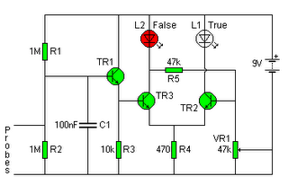
The following circuit illustrates a Lie Detector Circuit Diagram. Features include a capacitor that eliminates the 50Hz induced mains hum present in the circuit. The Lie Detector Circuit operates on the principle of measuring physiological responses, typically galvanic skin response...
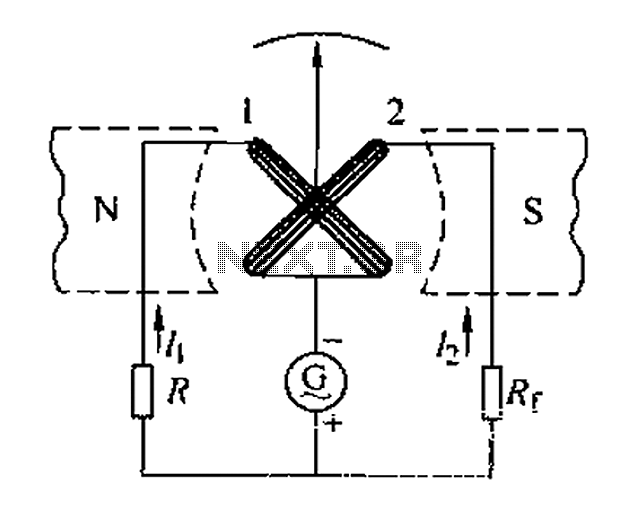
Also known as a megger insulation resistance meter, this device measures resistance at the megohm level. It is primarily used to assess the insulation resistance of motors, electrical circuits, and equipment. Additionally, it helps determine whether there is circuit...
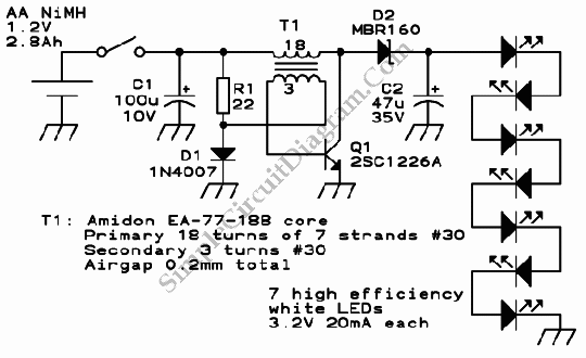
This is a single-cell LED flashlight circuit. This circuit utilizes a white LED that achieves optimal power efficiency at approximately 20 mA and requires about 3.3 V. The single-cell LED flashlight circuit is designed to provide efficient illumination using a...
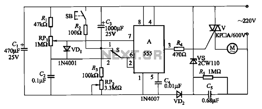
The circuit illustrated in Figure 3-12 incorporates variable speed and timing control functions. When switch S is set to position 1 and button SB is pressed, the motor initiates operation. After a predetermined delay, the motor automatically shuts down....

The TDA1029 is a dual operational amplifier configured as an impedance converter. Each amplifier features four mutually switchable inputs that are safeguarded by clamping diodes. Signal sources can be switched in various modes. The electronic components required for this...
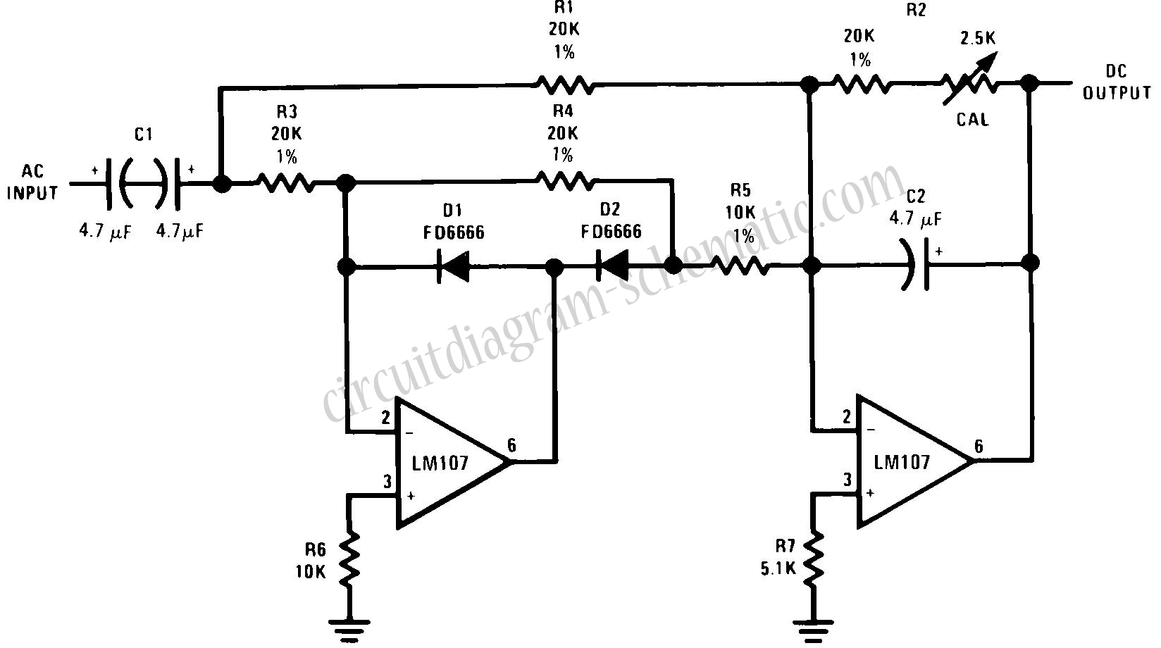
This circuit is an RMS-calibrated AC voltmeter that provides average readings. Removing capacitor C2 eliminates the averaging function, resulting in a precision full-wave rectifier, while removing capacitor C1 transforms the circuit into an absolute value generator. The operation of...
Warning: include(partials/cookie-banner.php): Failed to open stream: Permission denied in /var/www/html/nextgr/view-circuit.php on line 713
Warning: include(): Failed opening 'partials/cookie-banner.php' for inclusion (include_path='.:/usr/share/php') in /var/www/html/nextgr/view-circuit.php on line 713