
SensorCircuit Of Lie Detector
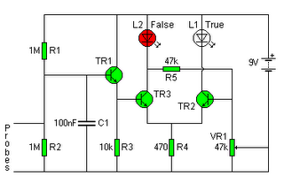
The Lie Detector Circuit operates on the principle of measuring physiological responses, typically galvanic skin response (GSR), to determine truthfulness. The circuit is designed to detect minute changes in skin conductivity, which can vary with emotional states.
Key components include a high-impedance operational amplifier, which amplifies the small variations in skin resistance. A capacitor is strategically placed in the circuit to filter out 50Hz noise commonly introduced by AC mains, ensuring that the readings are accurate and not influenced by external electromagnetic interference.
The circuit typically includes a voltage divider configuration that allows for the measurement of skin resistance. When a subject experiences stress or anxiety, their skin resistance decreases, leading to a measurable change in the output voltage of the operational amplifier.
Additional components may include a microcontroller for data logging and analysis, as well as visual indicators such as LEDs to provide immediate feedback on the subject's physiological state. The output can be further processed to produce a more comprehensive analysis of the subject's responses, enhancing the overall effectiveness of the lie detection process.
Overall, the Lie Detector Circuit is a sophisticated assembly of electronic components that work together to provide insights into human emotional responses, making it a valuable tool in various applications, including psychological research and security screenings.The following circuit shows about Lie Detector Circuit Diagram. Features: capacitor and removes the 50Hz induced mains hum that is found on a .. 🔗 External reference
Related Circuits
In the absence of radiation, no current is drawn. At normal background radiation levels, the power consumption is extremely low. The instrument may be left on for several months without changing batteries. In this way, the detector is always...
Processor-based systems typically require a voltage supervisor chip to generate a clean reset pulse for the processor whenever a brown-out condition in the power supply is detected. More complex designs that utilize multiple power supplies can become unreliable if...
Similar to a field strength meter, an RF detector circuit serves as a valuable project for detecting nearby RF signals. The circuit presented here is capable of detecting a wide range of RF frequencies and provides an alarm when...
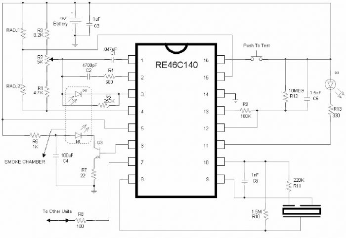
The RE46C140 circuit can be utilized to design a simple smoke detector alarm with minimal external electronic components. The RE46C140 integrated circuit (IC) is a low-power CMOS photoelectric smoke detector IC that encompasses all necessary features for a photoelectric...

The circuit utilizes a dual operational amplifier integrated circuit (IC), specifically the 1458, which contains two separate op-amps within a single package. In this configuration, the first op-amp functions as a voltage follower, directing its output to charge capacitor...
The diagram illustrates a simple and efficient receiver designed for activating garage doors, starter motors, alarms, warning systems, and various other applications. The SCR utilized in this circuit features an extremely low trigger current of 30 µA, requiring only...
Warning: include(partials/cookie-banner.php): Failed to open stream: Permission denied in /var/www/html/nextgr/view-circuit.php on line 713
Warning: include(): Failed opening 'partials/cookie-banner.php' for inclusion (include_path='.:/usr/share/php') in /var/www/html/nextgr/view-circuit.php on line 713