
12W Amplifier Using 741 Op Amp
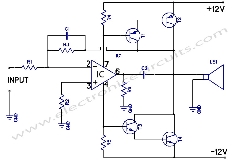
The 12W amplifier circuit utilizing the 741 operational amplifier is designed to deliver audio amplification at a power level of 12 watts. This circuit operates with a dual symmetrical power supply, typically providing ±12 volts, which is essential for achieving the necessary output performance and linearity.
The heart of the circuit is the 741 op-amp, which is configured in a non-inverting amplifier configuration to enhance the audio signal. The input signal is fed into the non-inverting terminal of the op-amp, while the output is taken from the op-amp's output pin. Feedback is provided from the output to the inverting terminal through a resistor network, which sets the gain of the amplifier. The gain can be adjusted by changing the resistor values in the feedback loop, allowing for customization based on the desired output level.
Additional components in the circuit include coupling capacitors at the input and output stages to block any DC offset and ensure that only the AC audio signal is amplified. A bypass capacitor may also be used to stabilize the power supply and reduce noise, enhancing the overall performance of the amplifier.
The output stage typically employs a complementary push-pull transistor configuration to deliver the necessary power to drive speakers effectively. This configuration helps to improve efficiency and reduce distortion, ensuring high-quality audio reproduction.
Thermal management is also a critical aspect of the design, as the output transistors can generate heat during operation. Adequate heat sinking should be implemented to maintain reliable operation and prevent thermal shutdown.
In summary, the 12W amplifier circuit using the 741 op-amp is a robust design suitable for various audio applications, providing a balance of performance, simplicity, and efficiency. Proper component selection and layout considerations are essential for optimizing the amplifier's performance and reliability.12W Amplifier Circuit Using 741 Op Amp A 12 watt audio amplifier operating on a dual symmetrical supply of ± 12 volts. The 741 provides the.. 🔗 External reference
Related Circuits
This circuit consists of wideband RF amplifiers that utilize current-feedback components such as the THS3202. The THS3202 was selected for its fast slew rate and wide bandwidth. The amplifier voltage gain of this circuit is 20, while the stage...
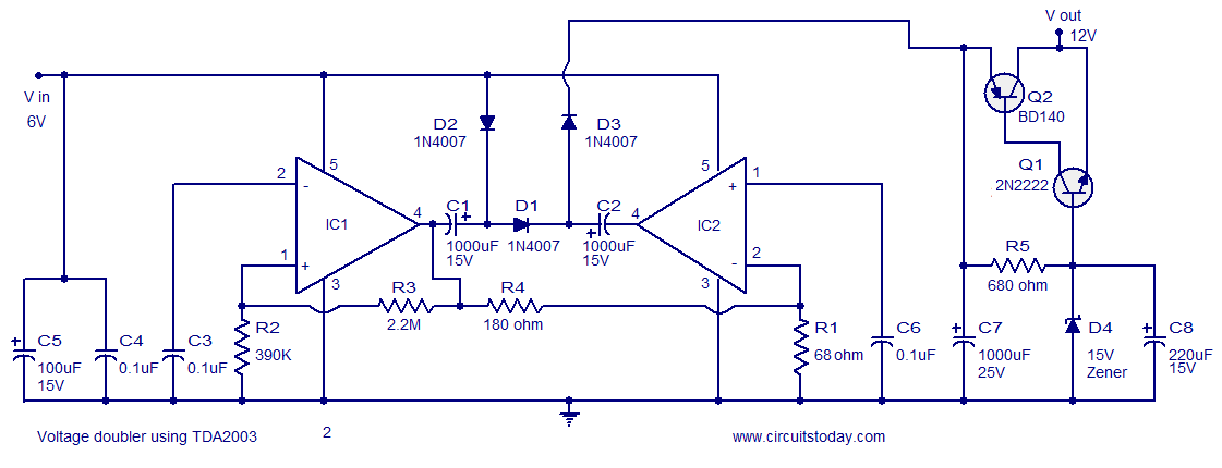
A reliable voltage converter circuit that operates between 6 to 12 volts, utilizing the audio amplifier IC TDA 2003. This voltage doubler circuit can be assembled on a Vero board. The voltage converter circuit designed with the TDA 2003 audio...
This FM RF amplifier utilizes two transistors from Philips: the BLV 10 and the BLW 87. The two RF transistors are configured in a chic C arrangement, providing an overall gain of 21 dB (100 times) with an efficiency...
Even if simple, the circuit meets all conditions regarding distortion and frequency response. The input resistance is 250K ohms, and it can drive loads between 100 ohms and 2K ohms. The described circuit is a basic signal processing circuit designed...
Activated this and inadvertently destroyed several 2N3055 transistors by shorting the emitters to ground. In all cases, the transistors opened up, and no damage to the emitter occurred in any transistor. The alternative circuit in Figure 2 will provide...
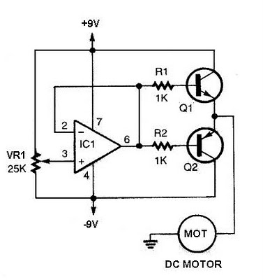
The speed increases in either direction as the potentiometer VR1 is adjusted toward its ends. The TIP3055 Q1 NPN power transistor has a collector current specification of 15A and a VCE0 rating of 60V DC. The MJE34 Q2 PNP...