
infrared emitter and detector using ic 74ls14

The line detection circuit primarily employs an infrared (IR) transmitter and receiver configuration, where the IR LED emits light that reflects off surfaces and is detected by a phototransistor. The effectiveness of this setup hinges on the alignment and calibration of the components. The IR light's reflection characteristics can vary based on the surface properties of the detected object, necessitating adjustments to the sensitivity of the phototransistor.
To enhance the circuit's functionality, it may incorporate a microcontroller to process the signals from the phototransistor. This microcontroller can analyze the received signals and determine whether an object is present based on the intensity of the reflected IR light. The logic can be programmed to trigger specific actions, such as stopping the robot or navigating around obstacles.
For calibration, the circuit should include variable resistors to adjust the sensitivity of the phototransistor. This allows for fine-tuning based on environmental conditions and the specific characteristics of the surfaces being detected. Moreover, the use of a laser pointer can improve detection accuracy over longer distances, providing a clear and focused beam that enhances the reliability of the detection mechanism.
In practical applications, the circuit can be integrated into a mobile robot platform, enabling it to navigate autonomously while avoiding obstacles. The simplicity of the IR transmitter and detector pair makes it an accessible choice for hobbyists and professionals alike, while the potential for expansion through microcontroller integration allows for more complex behaviors and functionalities in robotic systems.This circuit have applied to line detection of robot project, Good match between the transmitter and the detector is important for proper operation, especially if the hole is large. Robot with a simple object or obstacle detection. Infrared Transmitter detector pair sensors are relatively easy to implement, although involved some degree of testing
and calibration in order to make correct. They can for the impediment, motion detection, transmitters, encoders are used, and the color detection. This can be done with a piece of rope stretched between and in accordance with LED and phototransistor.
A length of stiff wire or plugs can be used to set the alignment. Another method that can be used for long distances is a laser pointer shone through a hole. 🔗 External reference
Related Circuits
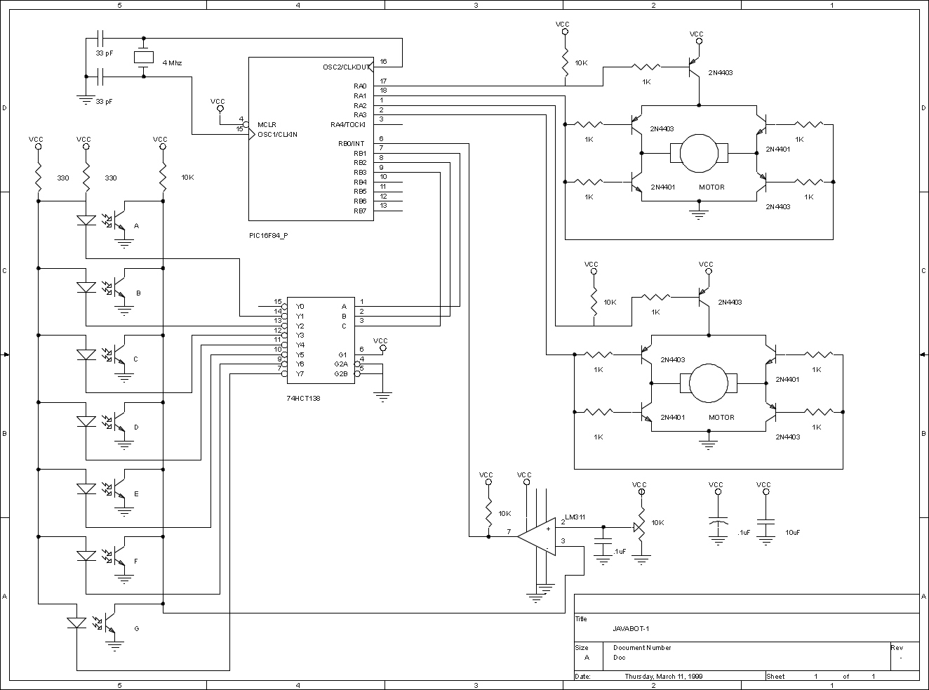
The JavaBot1 is a compact line-following robot engineered to trace a black line drawn on a dry erase board. It is specifically designed to navigate along very narrow curves. The JavaBot1 employs a differential drive mechanism, which allows it to...
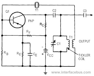
This circuit represents a variant of an Armstrong Oscillator. This specific example incorporates a crystal along with the LC tank circuit utilized in the previous Series-Fed Armstrong Oscillator. By definition, the Armstrong Oscillator employs a tickler coil for feedback...
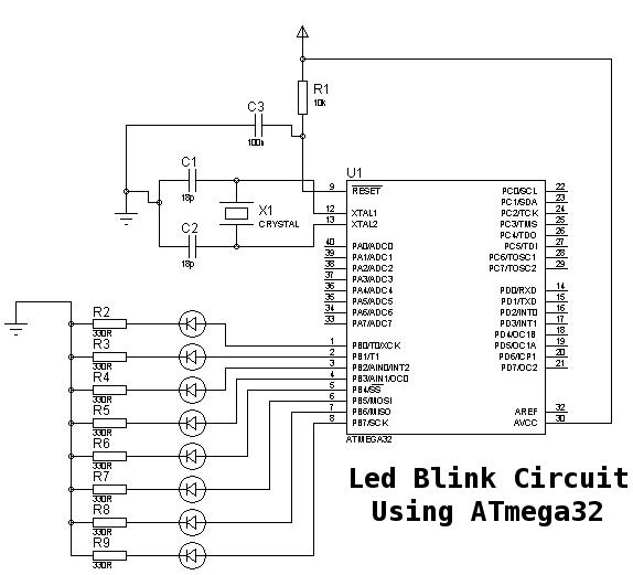
This is a basic tutorial for beginners using the ATmega32 microcontroller to get started. This program can be referred to as a "Hello World" for the ATmega. The ATmega32 microcontroller is a member of the AVR family, widely utilized in...
This circuit diagram for a 12V inverter is straightforward to construct, utilizing inexpensive components that many electronics hobbyists may already possess. While it is feasible to design a more powerful circuit, the complexity associated with handling high currents on...
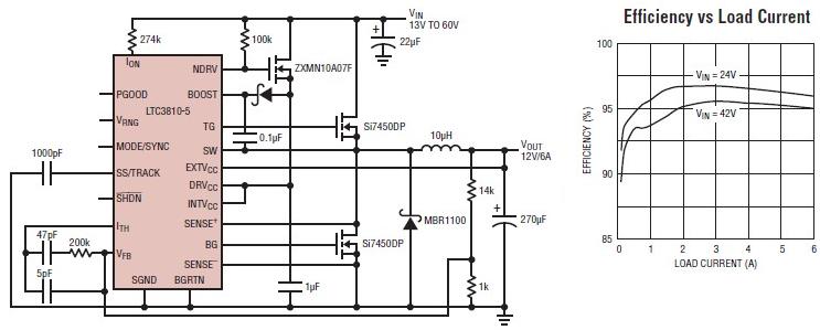
The LTC3810-5 synchronous step-down switching regulator controller can be used to design a simple and efficient 12-volt switching power supply electronic project with minimal external components. This controller is capable of stepping down voltages from up to 60V, making...
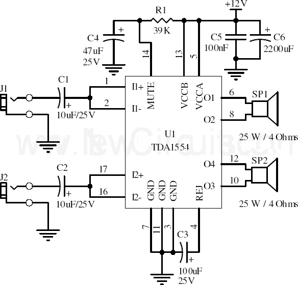
This document presents a 22-watt stereo audio power amplifier circuit diagram utilizing the TDA1554 integrated circuit from NXP Semiconductors (formerly known as PHILIPS Semiconductors). The circuit is designed to amplify stereo signals effectively. It dissipates approximately 28 watts of...
Warning: include(partials/cookie-banner.php): Failed to open stream: Permission denied in /var/www/html/nextgr/view-circuit.php on line 713
Warning: include(): Failed opening 'partials/cookie-banner.php' for inclusion (include_path='.:/usr/share/php') in /var/www/html/nextgr/view-circuit.php on line 713