
Light Related
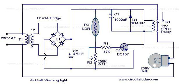
A low-cost circuit can be implemented to create a warning light atop tall structures to alert low-flying aircraft. Typically, such lights remain continuously lit; however, this design features a flashing light, which enhances visibility and safety. When the AC mains is activated, the bulb receives power and illuminates. As the bulb lights up, the adjacent light-dependent resistor (LDR) is also illuminated, causing its resistance to decrease. This change increases the voltage drop at the base of transistor Q1.
This circuit is a modification of the previously posted Simple Lamp Dimmer/Fan Regulator. The operation remains consistent with the earlier design, but a snubber circuit comprising resistor R4 and capacitor C3 has been added to enhance the performance of triac T1. A fuse is also incorporated for improved safety. The circuit is recommended for loads such as lamps, fans, or heaters, provided they are rated at less than 200 watts.
A light-activated switch circuit diagram utilizes the National Semiconductor comparator IC LM311 and an LDR. This circuit operates as a voltage comparator, where the non-inverting input of IC1 receives a reference voltage of 6V through resistors R3 and R4. The inverting input receives the voltage across the LDR, which is light-dependent. In darkness, the LDR’s resistance is high, resulting in a higher voltage across it.
The musical light chaser circuit is a straightforward yet advanced design suitable for discotheques or home use for music enthusiasts. The circuit operates by utilizing a condenser microphone to capture sound, which is then amplified by Q1. This amplified signal is directed to the clock input of IC1, CD4016, configured in divide-by-ten mode. The output from IC1 feeds into the clock input of IC2, CD4016, with the outputs of IC2 controlling the lighting.
The lamp flasher circuit operates from mains power and can flash lamps rated up to 200 watts at user-defined rates. The NE555 IC is configured as an astable multivibrator to generate the flashing pulses. The flashing rate is adjustable by modifying the values of resistors R2 and R3. Diodes D1 and D2 provide a half-wave rectified regulated supply for the IC. Transistor T1 drives the triac BT136, which controls the load, while resistor R4 limits the base current to Q1.
The touch control lamp dimmer circuit is a simple design utilizing the IC TT6061, specifically engineered for dimming applications. By touching the dimmer plate, the light intensity of incandescent lamps can be adjusted in three stages. Initially, when the mains power is on, the lamp remains off. The first touch activates a dim glow, the second touch increases the brightness to a medium level, and the third touch fully illuminates the bulb. A subsequent touch will turn the light off. The line frequency is detected through R4, connecting to pin 2 of the IC, allowing the IC to trigger at zero crossing.Watch the video given below to get a better idea on how LED works A light emitting diode (LED) is known to be one of the best optoelectronic devices out of the lot. The device is capable of emitting a fairly narrow bandwidth of visible or invisible light when its internal diode junction attains a forward electric current or voltage.
The visible l ights that an LED emits are usually orange, red, yellow, or green. The invisible light includes the infrared light. The biggest advantage of this device is its high power to light conversion efficiency. That is, the efficiency is Introduction. Here is low cost circuit that can be used for implementing a warning light on the top of tall structures as a warning for low flying aircrafts. Usually such lights are just stay glow type. Here our light is a flashing type, and surely this will draw more attention and of course add more safety.
When the AC mains is switched on the bulb will get supply and it will glow. When the bulb glows the LDR adjacent to it gets illuminated and it`s resistance drops. This will increase the voltage drop at the base of transistor Q1 and This is a modification of the circuit Simple Lamp Dimmer/Fan Regulator previously posted here. The working of the circuit is same as that of the previous, but in addition a snubber circuit consisting of resistor R4 and capacitor C3 is included to improve the performance of the triac T1.
A fuse is also included for better safety. I think this is the better circuit to try. Circuit diagram with Parts list. Notes. No matter how what ever may be the load lamp, fan, heater or anything it should be rated less than 200 Watts. No matter how A Simple Light activated switch This is the circuit diagram of a light activated switch based on National Semiconductors comparator IC LM 311 and a LDR.
The circuit is based on a voltage comparator circuit wired around IC 1. The non inverting in put of IC1 is given with a reference voltage of 6V using resistors R3 and R4. The input to the inverting input will be the voltage across the LDR that is light dependent. At darkness the resistance of the LDR will be high and so do the voltage across it. At this condition the voltage at the Musical Light Chaser Description Here is a simple state of the art musical chaser circuit that can be used in discotheques or even at home if you are a little music crazy. The working of the circuit is straight forward, the condenser mic pickup the sound and Q1 amplifies it.
This signal is fed to clock input of IC1, CD 4016. The IC is wired in divide by ten mode. The out put of IC1 is given to clock input of IC2, CD4016. The out puts of IC 2 shown in the right side of IC2 in circuit diagram will run Lamp Flasher using NE 555 Description This is the circuit diagram of lamp flasher operated from mains. By this you can flash up to 200 Watt lamps at rates determined by you. IC NE555 is wired as an astable multivibrator for producing the pulses for flashing the lamp. The flashing rate can be set by the value of resistors R2 & R3. Diodes D1 & D2 provides a half wave rectified regulated supply for the IC. Transistor T1 is used to drive triac and triac BT136 for driving the load. Resistor R4 limits the base current of Q1. Flashing Circuit Touch Control Lamp Dimmer Description This is a simple touch dimmer circuit made of IC TT6061.
TT 6061 is specifically designed for this purpose. By touching this touch dimmer you can increase the light intensity of incandescent lamps in three steps At first, when mains is on, ` the lamp is off`. When you touch the plate, the lamp glows dimly. At second touch, the bulb gives medium light. On the third touch, the bulb is driven fully. Next touch puts off the light off. Line frequency is taken through R4 to pin 2 of IC. At zero crossing the IC fires a 🔗 External reference
Related Circuits
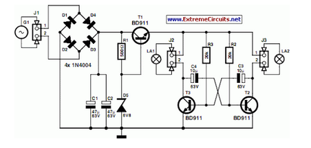
A front wheel with a built-in dynamo was purchased, providing a sine wave output of 30 Vpp at no load. Based on this, a simple power supply was designed using BD911 transistors, which are somewhat oversized for the application,...
The circuit below turns on a light corresponding to the first of several buttons pressed in a "Who's First" game. Three stages are shown but the circuit can be extended to include any number of buttons and lamps. Three...
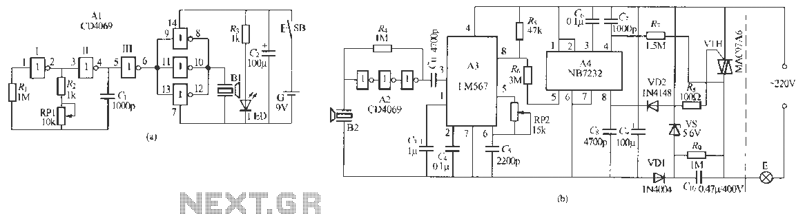
Remote control dimmer lights consist of two parts: an ultrasonic transmitter and an ultrasonic remote control dimmer receiver. The ultrasonic wave transmitter circuit is detailed in A 229 (a). It includes components such as R, R., RP1, and C,...
The circuit shown here is used to switch on a lamp when the telephone rings, if the ambient light is insufficient. The circuit uses only two ICs and it can be implemented very easily. A light dependent resistance (LDR),...
The circuit of a compact and true solid-state automatic lawn light is described here. The circuit can be used to switch on incandescent garden light bulbs. The described circuit functions as an automatic control system for garden lighting, specifically designed...
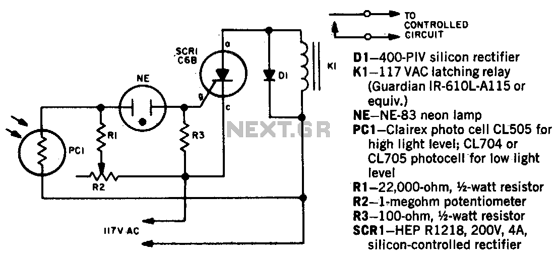
When a beam of light strikes the photocell, the voltage across the neon lamp NE-1 rises sharply. NE-1 turns on and triggers the SCR. K1 is an impulse relay whose contacts remain in position even after the coil current...