
Light beam operated on-off relay
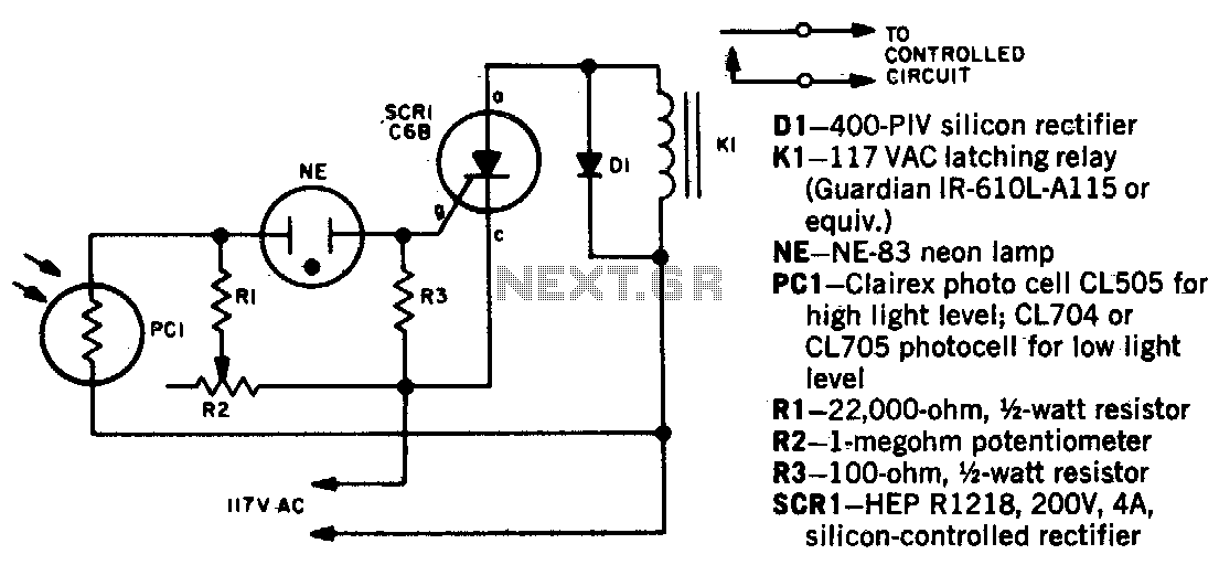
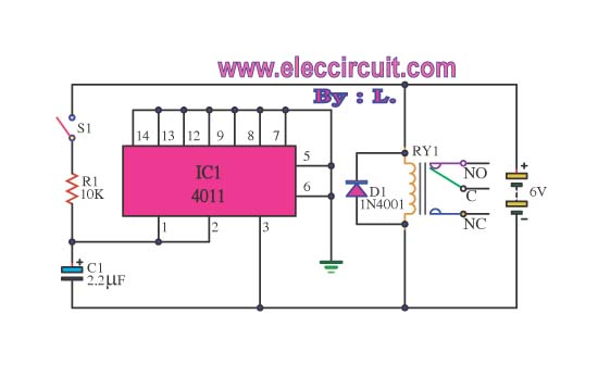
The circuit described involves a photocell that serves as a light sensor, detecting the presence of light. Upon activation by a light beam, the photocell generates a voltage that increases significantly, causing the neon lamp NE-1 to illuminate. The neon lamp functions as a visual indicator and also plays a critical role in the triggering mechanism of the silicon-controlled rectifier (SCR).
When NE-1 is activated, it provides sufficient gate current to the SCR, allowing it to conduct and complete the circuit. This conduction allows current to flow through the relay K1, which is designed as an impulse relay. The operation of K1 is characterized by its ability to maintain its contact position after the initial coil current is removed, thanks to its latching mechanism.
The operation sequence begins with the first light impulse that opens the contacts of relay K1, which can control other devices or circuits connected to its output. Upon receiving a second light impulse, K1’s contacts close again, allowing for a toggle action that can be repeated. This on-off control mechanism enables the circuit to perform various functions, such as controlling lights or other electrical devices based on light detection, providing a practical application in automation systems.
This circuit exemplifies the integration of light sensing, visual indication, and relay control, showcasing a simple yet effective method for creating automated responses to environmental changes.When a beam of light strikes the photocell, the voltage across neon lamp NE-1 rises sharply. NE-1 turns on and fires the SCR. Kl is an impulse relay whose contacts stay in position even after coil current is removed The first impulse opens Kl"s contacts, the second impulse closes them, etc. 🔗 External reference
Related Circuits
Here's a power-on time delay relay circuit that takes advantage of the emitter/base breakdown voltage of an ordinary bi-polar transistor. The reverse connected emitter/base junction of a 2N3904 transistor is used as an 8 volt zener diode which creates...
This is an automatic LCD panel backlight control circuit. It is a simple, low-cost implementation of an LED controller that can compensate for aging effects. The automatic LCD panel backlight control circuit is designed to enhance the performance and longevity...
The 555 timer IC is connected for Astable Operation, the clock pulses are fed to the 4017 IC via the 10K resistor. The 4017 is a 10 stage counter, each of the outputs is connected to the appropriate LED,...
I ride my bike allot at night and sometimes I'm not sure if people can see me. This circuit will flash an incandescent light that you can purchase from Radio Shack. Adjust the VR's for your flash requirements and...
This circuit can be utilized to delay other appliances connected to the output of the relay. It operates to prevent equipment damage. This circuit is designed to provide a delay mechanism for appliances that are connected to a relay output....
Circuit schematics for the 555-based PLL laser light PFM receiver. Although R4 is shown as a resistor, it is advisable to replace it with a 10-kΩ precision potentiometer to allow for fine-tuning of the transmitter's center frequency. Experimentation with...