
Ultrasonic remote control dimmer light circuit
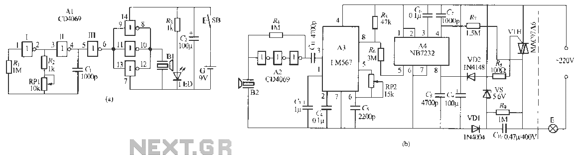
The ultrasonic remote control dimmer circuit is illustrated in Figure 229 (b). The main circuit comprises an ultrasonic transducer that receives the ultrasonic signal, a decoder, dimming IC, and other components. Transducer B2 supports the ultrasonic receiving transducer, which converts the incoming ultrasonic signal into a corresponding electrical signal. The signal is amplified by amplifier A2, which consists of CMOS digital integrated circuits (CD1069) arranged in series through R, forming a linear amplifier with a total gain exceeding 60 dB. The ultrasonic transducer, primarily a piezoelectric ceramic element, has a high output impedance, making the CMOS amplifier an effective match for improved reception sensitivity.
Amplifier A3 functions as a phase-locked loop audio decoder (LMS67). When the frequency of the input signal approaches its center frequency, A3's logic output transitions, generating a negative pulse that is sent to optical integrated circuit A4 (NH7232). This output serves as the trigger for completing the lamp operation, whether to turn it on or off. The center frequency is determined by resistors R1, R2, and capacitor RP2, which collectively set the frequency to approximately 10 kHz. The first pin SFN serves as a low effective trigger level, and when the trigger signal is within 0.3 seconds, it executes the lamp operation. If the low time output from A3 exceeds 0.3 seconds, the circuit can achieve stepless dimming. The conduction angle of the thyristor VTH can be adjusted between 41° and 159°; at 49°, the light is dimmed, while at 159°, it is at maximum brightness.
The circuit includes two terminals that can be directly substituted for a standard switch, effectively transforming it into a remote control system. Amplifiers A1 and A2 can utilize D4069 inverter-type integrated circuits, with A2 employing only three of the six inverters, while the remaining three must be grounded to prevent interference. A4 may be replaced with an NH7732 or similar integrated circuit for touch dimmer functionality. Transducers B1 and B2 are paired with TCT40 12F and TCT40 12S2 piezoelectric ceramic ultrasonic transducers, respectively. Other component parameters are standard and do not have special requirements.Remote control dimmer lights consist of two parts ultrasonic transmitter and ultrasonic remote control dimmer receiver components, ultrasonic wave transmitter circuit, see A 229 (a). Non-fj l, and R, R., RP1 and C. Composition White clamor excited multivibrator, generates the oscillation signal 40kliz. By NAND gate s shaping , and then by three parallel NAND gates scaled directly driving the ultrasonic transmitter transducer B1 to Li nosebleed acoustic radiation. A light emitting diode IF: D with transmitters to refer months i work state, when press F hair shot button SB I31 namely stroke emission 40kjIz ultrasound, when "Division I, ED lit light indication.
Si light receiving ultrasonic remote control din circuit shown in Figure 229 (b), the main circuit is received by the ultrasonic transducer, ultrasonic crossing signal release composition, decoder, dimming IC and other components. B2 and Bl foot supporting ultrasonic receiving transducer, it receives iUkHz ultrasound from the emitter signal is about to convert it into a corresponding electrical signal.
Ultrasound // 1 / amplifier A2 by the CMOS digital integrated circuits (CD1069) composed of NAND gates in series and will only be through R. That constitutes a linear amplifier bias-cho, a total gain of more than 60dB. Ultrasonic transducer 13 Star piezoelectric ceramic element substantially higher output impedance, so using CM () S amplifier can be a good match with their catch, so that the circuit has high reception sensitivity.
A3 for the phase-locked loop audio decoder (LMS67), when the frequency of the input signal is feet just fall its center frequency, A3 of the first logic output that is caused by mutations feet high on low, quite to output a negative pulse, added to by R a Si optical integrated circuits A4 (NH7232) That is the end of the first Sl ~~ feet, Al trigger as to complete the "+ f", "off" or stripped lamp operation. A3 center frequency by RI, 2 and (i decision value, i.e.,: . F = L, (1 1RP2C :), the whole inner room RP2 m values that the center frequency only good butoxy 10kHz: .4 first pin SFN is low effective trigger level phase shift control input when the trigger signal is within 0 3s, to be completed by "open" and "curse" lamp operation.
If the low time pin output A3 of the big 0 3s. can be realized stepless split light operation, VTH thyristor conduction angle will be adjusted in 41-159 'of when the conduction angle is 49. when, Gui E borers dark; ilfi angle is 159. Gan, the brightest of the lights. Foreign withdraw only two circuit terminals, heir where it can be directly substituted verbale called switch, which was transformed into the remote Ba j dagger Chan.
A1, A2 can be employed (:. D4069 6 inverter type in the number of integrated circuit receiving Ning vessel, A2 actual use on only three of them intact inverter, the other three do not have non-f J should be grounded at all input processing, which do not float, so as to avoid interference .A4 to ten NH773 2 type CS7232 or touch dimmer integrated path .Bi, H2 respectively supporting TCT40 12F TCT40 12S2 and piezoelectric ceramic ultrasonic transducers. other component parameters Figure, no special requirements spider.
Related Circuits
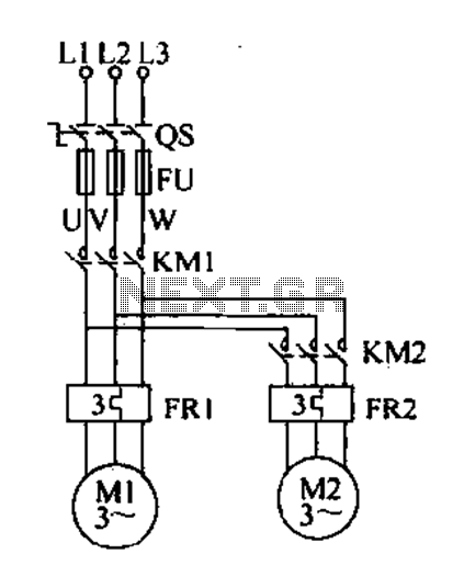
Delay starting a motor control circuit The motor control circuit designed for delayed activation incorporates a timing mechanism that ensures the motor does not start immediately upon receiving power. This is particularly useful in applications where a staggered startup...
The circuit is directly connected to the AC power line and should be placed inside an enclosure that will prevent direct contact with any of the components. To avoid electrical shock, do not touch any part of the circuit...
The circuits in Figure 1 and Figure 2 demonstrate specific advantages over the circuit presented in the Design Idea in EDN, titled "Circuit detects first event," published on May 3, 2001, page 89. The n-player first-event detection circuit provides...
Dimmer Switch - Dimmer Switch Working, Installation, Circuits and Explanation. A dimmer switch is a device that allows for the adjustment of the brightness of a light fixture. It operates by varying the voltage and current supplied to the light...
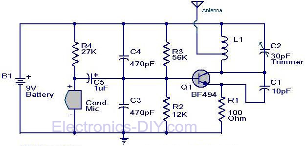
The circuit diagram of a simple FM transmitter utilizing a transistor is presented. While this design may not guarantee exceptional performance or range, it serves as a fundamental example. The circuit employs a general-purpose radio frequency transistor, the BF...

Voltage regulator ICs (78xx series) provide a steady output voltage, in contrast to a widely fluctuating input supply, when the common terminal is grounded. The 78xx series of voltage regulator integrated circuits (ICs) are widely utilized in electronic circuits to...