
Light Sensor Switch Circuit
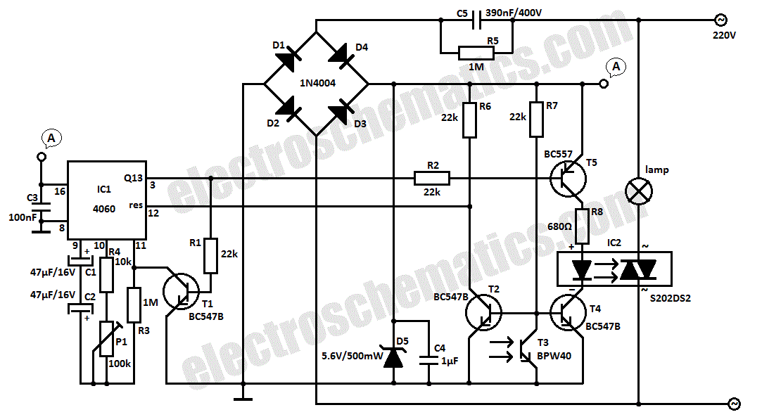
The light sensor switch circuit operates on a straightforward principle, primarily utilizing transistors and a relay to control the lamp based on ambient light conditions. The circuit is designed to function effectively without an external power source, drawing energy directly from the mains supply, which simplifies installation and reduces the need for additional components.
The main components include the phototransistor T3, which acts as the light sensor, and the transistors T2, T4, and T5, which facilitate the switching mechanism. When the ambient light falls below a certain threshold, T3 conducts, allowing current to flow and enabling T5 to activate. This, in turn, energizes the relay, causing the lamp to turn on.
Resistor R7 plays a crucial role in the circuit by providing the necessary base current to T2 when the light levels are low. This allows T2 to conduct and reset the counter in IC1, which is responsible for timing the duration for which the lamp remains on. The internal oscillator within IC1 generates the timing pulses that dictate how long the lamp stays illuminated after T2 is activated.
The transition from the lamp being on to off is controlled by the output state of Q13. Once the counter reaches a predetermined count, Q13 outputs a high signal, which blocks T4, deactivating the relay and turning off the lamp. This feature ensures that the lighting is only active when needed, contributing to energy efficiency.
The rectification of the AC voltage is handled by diodes D1 through D5, which convert the 220V AC supply into a usable DC voltage for the circuit. Capacitor C4 smooths out the rectified voltage, providing stable power to the transistors and IC.
Overall, this light sensor switch circuit is an efficient and effective solution for automatic lighting control, leveraging simple electronic components to achieve reliable performance in low-light conditions.This light sensor switch circuit allows the automatic connection of a lamp when the light is low (at nightfall) and will maintain the lamp ON for a certain period of time. From the moment that T4 and T5 are opened, relay`s LED start to light and powers the lamp. As soon as one of the transistors is blocked the lamp will go OFF. The phototransistor T3 will be the one that blocks T5 if there is light that falls on T3. The T2 ²s base-emitter junction is connected in parallel with T3 and so will be blocked as long there is light. T2 will continuously reset IC1 whose counter outputs will be in 0 ³ state. When the night falls R7 provides base current for T2 and the transistor starts to conduct. The counter can now starts to count the impulses from the internal oscillator and in this time the light will bulb will stay lit.
After a time, when the output of Q13 goes in state 1 ³ T4 is blocked. This causes the relay`s LED to go off and the lamp too. There is no need for external power supply because the light sensor switch is powered directly from the 220V mains. D1 D5 diodes rectifies the voltage and C4 filters it. 🔗 External reference
Related Circuits
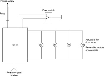
A central door locking system allows all doors, including the boot lid or tailgate, to be locked centrally from the driver's door, typically including the front passenger's door as well. The locking and unlocking actions are performed by an...
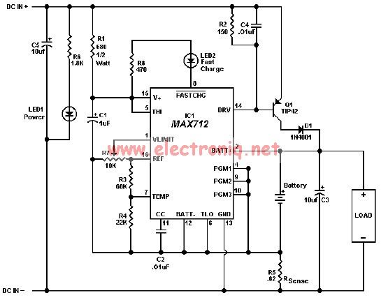
The MAX712 charger requires a power supply with an output voltage that is at least 1.5V higher than the maximum battery voltage. Charge completion is determined by a voltage-slope detecting analog-to-digital converter, a timer, and a temperature window comparator. The...
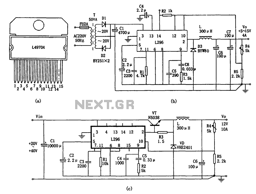
The L296 chip is a high-current switching power supply component designed to operate within a voltage range of 5 to 15V and provide an output current of up to 4A. This monolithic chip incorporates several features including enhanced protection...

The clock pulses from the 555 astable circuit are sent into the 4017 decade counter. Each output becomes high in turn as the clock pulses are received. Appropriate outputs are combined with diodes to supply the amber and green...
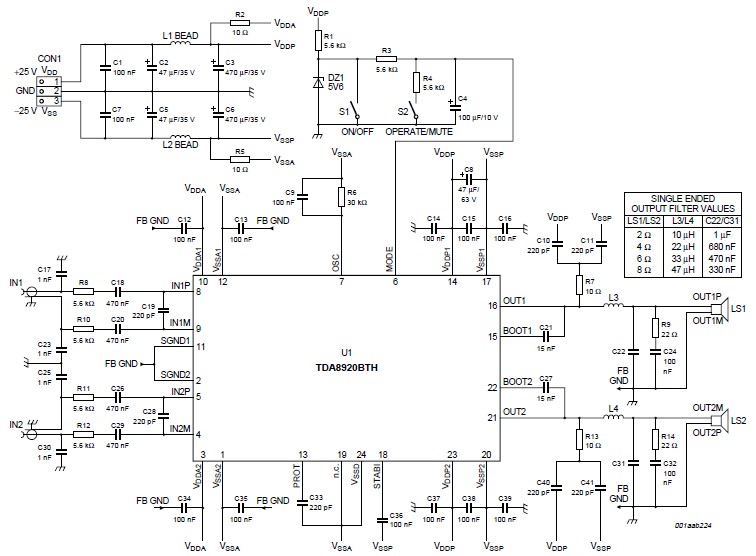
This high-power Class D audio amplifier electronic project utilizes the TDA8920BTH audio power amplifier integrated circuit (IC). This power amplifier IC is characterized by its high efficiency and low heat dissipation, delivering significant output power. The typical output power...
AM radio receivers demodulate amplitude-modulated (AM) signals. The primary source of these signals is the Standard AM Radio Broadcast Band, although shortwave stations also utilize AM modulation. Amplitude modulation was developed between 1900 and 1917 by amateur radio enthusiasts....
Warning: include(partials/cookie-banner.php): Failed to open stream: Permission denied in /var/www/html/nextgr/view-circuit.php on line 713
Warning: include(): Failed opening 'partials/cookie-banner.php' for inclusion (include_path='.:/usr/share/php') in /var/www/html/nextgr/view-circuit.php on line 713