
Build Basic Radio Frequency Electronic Circuits
To construct a loop antenna, use a single piece of 1x2 pine lumber measuring 6 feet long. Cut it in half to create two 3-foot sections. Find the center of each section and cut a slot that is 3/4 inch wide, extending halfway down each piece. Join the two sections to form an "X," possibly gluing them together. Insert two small wood screws side by side near the center of one cross arm to serve as the starting and ending points for the wire wound around the outside of the "X." Add two more screws on the opposite side for the coupling loop. Starting at one of the screws, wrap 26-gauge enameled copper magnet wire around the screw to secure it, then wind the main loop with six turns, leaving 6 inches of wire free before cutting. Repeat this process for the coupling loop, ensuring to leave 6 inches of wire free at both screws.
After construction, check all solder connections and ensure the transistor is connected correctly. With the volume control (VR1) turned down, switch on (S1) and gradually increase the volume. Since the radio lacks automatic volume control (AVC), nearby AM transmitters may produce a loud signal. Tune the radio using capacitor C1 until stations are heard, adjusting the loop for the strongest signal.
A dip meter is a versatile tool that can function as a signal generator, resonance indicator, AM detector, and more. The coil (L1) should be designed to plug into the oscillator, allowing for a wide frequency range. With multiple plug-in coils, coverage can extend from the AM broadcast band up to 2 meters. A communications receiver can substitute for a counter, ensuring that the fundamental frequency is detected rather than any harmonics from the meter. To find the resonant frequency of an LC circuit using the meter, hold the meter near the circuit while adjusting the components.
The circuit described is a fundamental AM radio receiver utilizing a simple loop antenna design for signal capture and a diode detector for demodulation. The loop antenna's construction emphasizes a straightforward approach to creating an effective receiving element without requiring complex materials or components. The use of a dip meter enhances the device's functionality, allowing for experimentation across various frequencies, which is particularly useful for amateur radio operators or electronics enthusiasts. The overall design fosters an understanding of AM signal reception and the principles of radio communication.AM radio receivers receive or demodulate amplitude modulated (AM) signals. The most common source of these signals is of course todays Standard AM Radio Broadcast Band but shortwave stations use AM modulation as well. Amplitude modulation was really developed between 1900 and 1917 by amateur radio experimenters ("hams").
Then when WW1 ended, comme rcial AM radio broadcasts began. Amplitude modulation means that the output power of a radio stations transmitter increases or decreases in accordance with the music or voice that is being transmitted. If we string out a length of wire, some of that transmitted energy will cause a small current to flow in our wire.
That current will increase and decrease in step with the modulation of the carrier wave and if we hook the wire to a diode detector, the detector will detect or demodulate the signal leaving only the audio. The loop antenna is made out one piece of 1X2 pine lumber 6 feet long. Cut the piece in half so that each section is now 3 feet long. Find the center of each and cut a slot the exact width width of the narrow dimension (3/4") on both sections the cut should extend down half way through the piece on each.
Now slide and tap the two sections together to form a "X". You may want to glue the two together. Insert two small wood screws side by side near the center of the "X" on one of the cross arms. This will be the starting and ending points for the wire that is wound around the outside of the "X" forming the main antenna. Now insert two more wood screws on the oposite side of the first two. This will be the starting and ending points for the single turn loop of wire that couples the main loop into the radio.
Starting at one of the two side by side screws, wrap the wire around the screw a few times to hold it and then begin to wind the main loop using 26 gauge enameled copper magnet wire. Leave at least 6 inches of wire "free" so you can connect later. Wind 6 turns of wire around the loop and then back down to the other screw, leaving 6 inches free again before cutting.
Try to keep the windings good and tight as you go around. Now beginning at one of the other two screws, begin winding a single turn of wire around the loop and again leave 6 or so inches of wire free at both screws. This is the coupling loop. (see schematic above) A word of warning. after you build this, be careful of walking down your street or even standing out in front of your house with the loop in your hands and old style headphones on your head.
Because your neighbors will think you are either some type of spy, or you are somehow listening in on them, or worse you are tracking space aliens! (from experience) After finishing construction check all solder connections, check again to be sure the transistor is connected correctly then turn the volume control VR1 all the way down.
This radio has no AVC (automatic volume control) so if you live near an AM transmitter the signal will be VERY loud as you tune it in. Turn on the switch S1 and carefully turn the volume control up to about half way. Now tune around with C1 until you begin to hear stations. Turn the loop until the signal is the strongest. To see what the finished loop antenna looks like, look back at the top of this article. There is a picture of me holding it. You can see capacitor C1 clearly. A dip meter is useful for so many things, that I don`t know where to start. It can be used as a signal generator, a resonance indicator, AM detector and more. The coil L1 should be made to plug in to the oscillator so you can use the meter over a very large frequency range.
With several plug in coils you could cover from the AM broadcast band up through 2 meters. A communications receiver could be used in place of the counter just be sure you are hearing the fundamental and not one of the many harmonics from the meter. To use the meter to find the resonant frequency of any LC circuit just hold th 🔗 External reference
Related Circuits
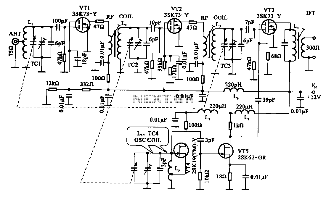
The FM radio circuit is represented by a double-gate MOS field-effect transistor. The high-frequency amplifier is a bipolar MOS field-effect transistor amplifier consisting of transistors VT1 and VT2. VT3 serves as the mixer. The local oscillator is formed by...
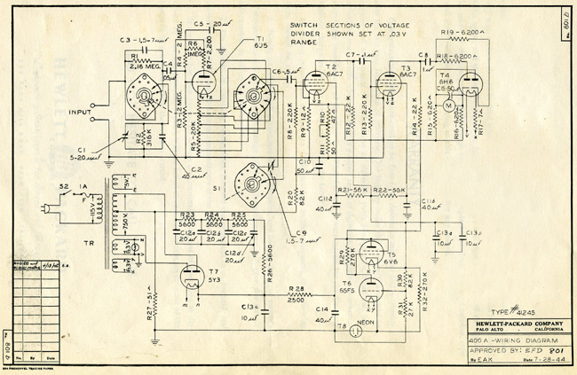
The HP Model 400A Vacuum Tube Voltmeter is highly versatile due to its extensive frequency and voltage ranges. It can directly measure AC voltages as low as 0.005 volts and as high as 300 volts across a frequency range...
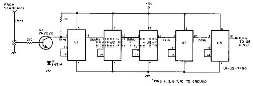
This circuit is designed to be driven by a 1-MHz standard signal with an amplitude of several volts. The components U1 through U5 are 7490 decade counters/dividers, providing a division ratio of 100,000:1. It is possible to tap off...
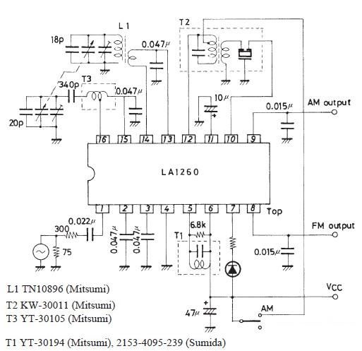
The FM IF MW radio receiver circuit schematic utilizes the LA1260 integrated circuit (IC) for AM and FM radio receiver electronic projects. The LA1260 incorporates numerous functions and features essential for radio receiver applications, including a high signal-to-noise ratio...
This page shows some methods of track routing control for Stall-Motor type switch machines. The principle method uses a 2 Pole - Multi Position rotary switch while an alternate uses optoisolators and transistors to select the routes. The last...
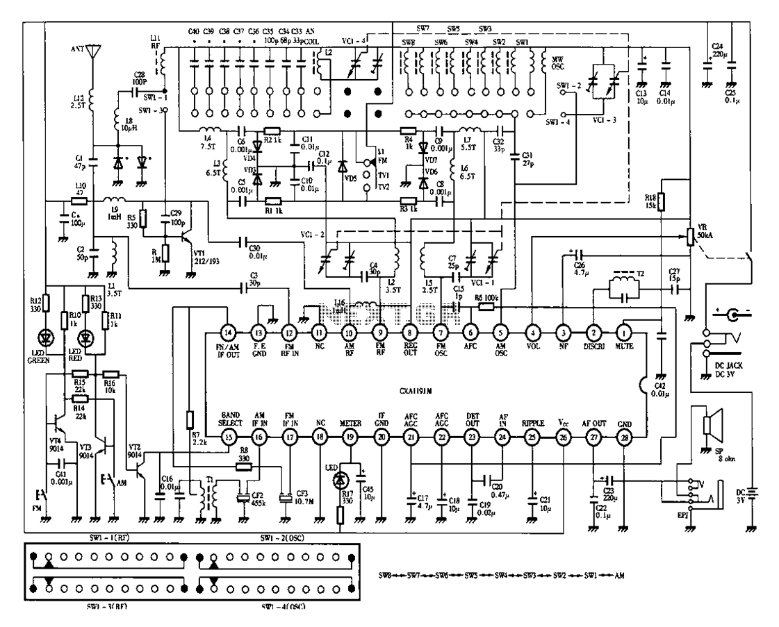
Desheng 1012 is a 12-band radio circuit diagram that covers FM, MW, SW, and TV sound frequencies. The Desheng 1012 radio circuit is designed to receive a wide range of frequencies across multiple bands, including FM (Frequency Modulation), MW...
Warning: include(partials/cookie-banner.php): Failed to open stream: Permission denied in /var/www/html/nextgr/view-circuit.php on line 713
Warning: include(): Failed opening 'partials/cookie-banner.php' for inclusion (include_path='.:/usr/share/php') in /var/www/html/nextgr/view-circuit.php on line 713