
electronics traffic light circuit

The circuit utilizes a 555 timer configured in astable mode to generate continuous clock pulses. The frequency of these pulses can be adjusted by changing the resistor and capacitor values connected to the 555 timer. The output from the 555 timer is fed into the clock input of the 4017 decade counter, which counts the incoming pulses and sequentially activates its outputs from Q0 to Q9.
As each output of the 4017 goes high in response to the clock pulses, it can be used to control various loads. In this specific design, the outputs of the 4017 are connected to diodes that facilitate the connection to amber and green LEDs. The use of diodes ensures that the current flows in the correct direction, preventing backflow and protecting the components.
To implement this circuit, the 555 timer is typically powered by a voltage supply within its operating range (usually between 4.5V and 15V). The resistors (R1 and R2) and capacitor (C1) are chosen to set the desired frequency of oscillation. The output from the 555 timer is connected to the clock input of the 4017, which is powered by a suitable voltage supply (up to 15V).
The outputs of the 4017 can be connected to the anodes of the LEDs, with the cathodes connected to ground through current-limiting resistors. The choice of resistor values will depend on the supply voltage and the specifications of the LEDs used to ensure they operate within safe limits.
This configuration allows for a visually dynamic display, with the LEDs illuminating in sequence as the decade counter cycles through its outputs. The design can be further enhanced by adding more LEDs, modifying the timing components for different pulse rates, or integrating additional circuitry for more complex applications.The clock pulses from the555 astable circuit is sent into the 4017 decade counter. Each output becomes high in turn as the clock pulses are received. Appropriate outputsare combined with diodes to supply the amber and green LEDs. 🔗 External reference
Related Circuits
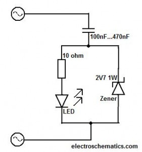
This circuit should only be attempted by individuals with a strong understanding of electronic devices. It is connected to a main power source (220V) and poses a risk of high electrical shock. This circuit operates at a mains voltage of...
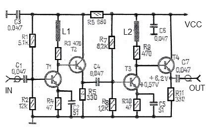
This antenna amplifier is effective for the frequency range of 35 kHz to 150 MHz. The circuit utilizes transistors and features a low 3 dB non-linearity along with a high gain of 43 dB. The input and output impedance...
This motor speed controller utilizes a single IC, the LM1014, to regulate the speed of a DC motor. It detects the increase in motor current as the rotation of the motor increases. The motor speed controller is designed around the...
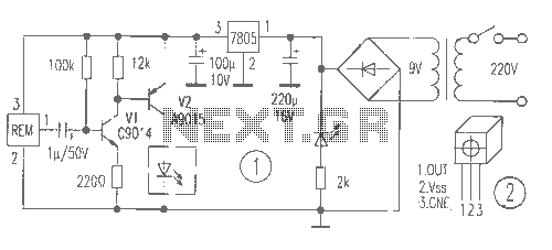
The receiver provides two TV signals, one for the living room and another for the bedroom, along with a satellite receiver. Watching television in the bedroom is convenient in Taiwan; however, when watching television in the living room, it...
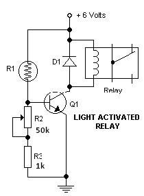
This light-dark switch activated relay circuit schematic represents one of the simplest electronic circuits designed to activate other electronic devices based on light or darkness. It requires a single electronic relay and a few common components that are not...
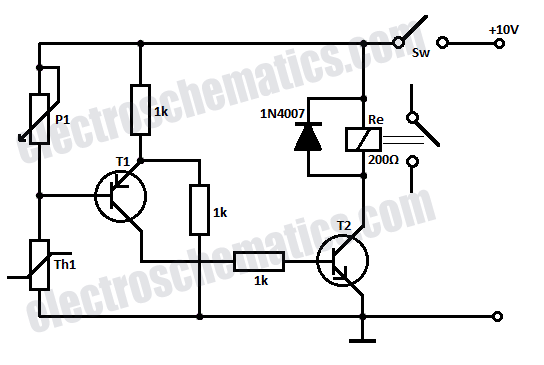
Safety is a significant concern in many motor-driven applications. This is particularly true in industrial settings where motion begins immediately upon the application of power. In motor-driven applications, safety mechanisms are essential to prevent accidents and ensure the well-being of...