
Light Sequencer schematic

Assuming the circuit does not start when power is applied and all lights are off with all three capacitors charged to approximately 5 volts, a jumper can be connected across the 220µF capacitor on the left. This action discharges the capacitor, turning on the second stage transistor and the corresponding light. Once the jumper is removed, the capacitor will begin to charge through the base of the stage 2 transistor and the stage 1 light. This charging process allows the stage 2 transistor to remain in the 'on' state while the capacitor continues to charge.
Simultaneously, the capacitor connecting stage 2 and stage 3 will discharge through a 100-ohm resistor and a diode, as well as through the stage 2 transistor. When the charging current through the capacitor falls below the threshold needed to keep stage 2 activated, the transistor and its associated light will turn off. This action causes the voltage at the collector of the stage 2 transistor to rise back to 5 volts. As the capacitor connecting stages 2 and 3 has discharged, the increase in voltage at the collector of the stage 2 transistor allows the capacitor from stage 2 to stage 3 to charge, thereby turning on the third stage and continuing the cycle for subsequent stages (4, 5, 6, 7, etc.) and eventually returning to stage 1.
The sequence rate of this light sequencer is determined by the values of the capacitors and resistors used (220µF and 100 ohms in this configuration), the load current (200mA), and the current gain of the specific transistors employed. This arrangement is capable of achieving approximately 120 complete cycles per minute for the three lights, translating to a duration of about 167 milliseconds per light. Adjusting the capacitor values can yield faster or slower sequencing rates, allowing for customization based on specific application requirements.The drawing below illustrates a multistage light sequencer using descrete parts and no integrated circuits. The idea is not new and I hear a similar circuit was developed about 40 years ago using germanium transistors.
The idea is to connect the lights so that as one turns off it causes the next to turn on, and so forth. This is accomplished with a large capacitor between each stage that charges when a stage turns off and supplies base current to the next transistor, thus turning it on.
Any number of stages can be used and the drawing below illustrates 3 small Christmas lights running at about 5 volts and 200mA. The circuit may need to be manually started when power is applied. To start it, connect a momentary short across any one of the capacitors and then remove the short. You could use a manual push button to do this. Detailed operation: Assume the circuit doesn't start when power is applied amd all lights are off and all three capacitors are charged to about 5 volts. We connect a jumper across the 220uF capacitor on the left which discharges the capacitor and turns on the 2nd stage transistor and corresponding light.
When the jumper is removed, the capacitor will start charging through the base of the stage 2 transistor and stage 1 light. This causes the stage 2 transistor to remain on while the capacitor continues to charge. At the same time, the capacitor connecting stage 2 and 3 will discharge through the 100 ohm resistor and diode and stage 2 transistor.
When the capacitor charging current falls below what is needed to keep stage 2 turned on, the transistor and light will turn off causing the voltage at the collector of the stage 2 transistor to rise to 5 volts. Since the capacitor connecting stage 2 and 3 has discharged and the voltage rises at the collector of stage 2, the capacitor from stage 2 and 3 will charge causing the 3rd stage to turn on and the cycle repeats for sucessive stages 4,5,6,7....
and back to 1. The sequence rate is determined by the capacitor and resistor values (220uF and 100 ohms in this case), load current (200mA in this case), and current gain of the particular transistor used. This arrangement runs at about 120 complete cycles per minute for 3 lights, or about 167mS per light.
Faster or slower rates can be obtained with different capacitor values. 🔗 External reference
Related Circuits
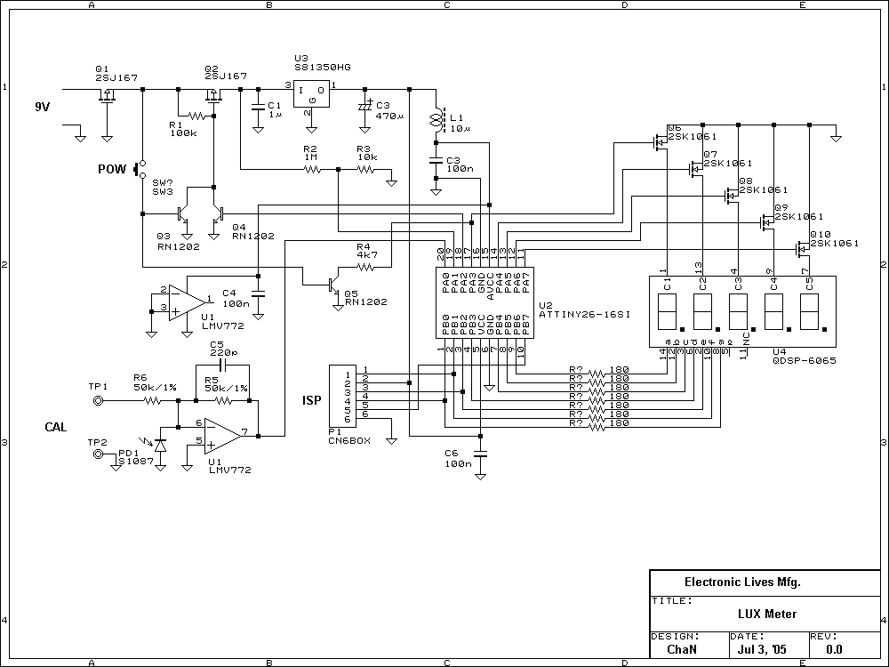
Lux meter circuit using an Atmel ATtiny26-16 microcontroller, which displays lux values on an LED display. The circuit utilizes 2SK1061 MOSFETs for driving the LEDs. The lux meter circuit operates by measuring ambient light levels and converting these measurements into...

The two circuits illustrate the generation of low-frequency sine waves by shifting the phase of the signal through an RC network, enabling oscillation when the total phase shift reaches 360 degrees. The transistor circuit on the right produces a...
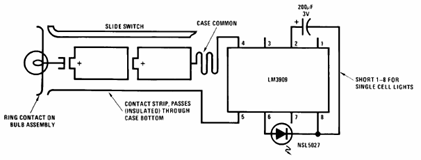
The schematic presented below illustrates the Flashlight Finder circuit diagram utilizing the LM3909, a monolithic oscillator specifically designed for flashing Light Emitting Diodes (LEDs). The Flashlight Finder circuit employs the LM3909 integrated circuit, which is capable of generating a series...
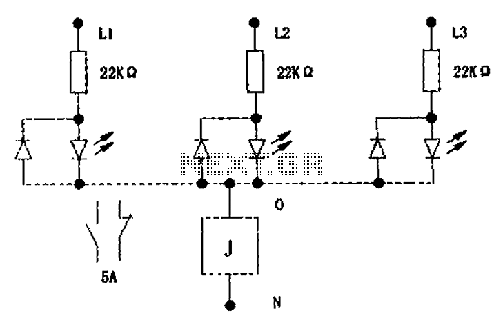
The circuit illustrated below activates a small relay (J) when there is an imbalance in any one phase of a three-phase circuit. This relay triggers an external control contact, which immediately disconnects the power supply to the main circuit...
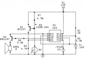
The IC 555 Light Alarm (Sun Up Alarm) circuit is designed to emit a loud alarm at dawn, particularly for individuals who struggle to wake up, even with a traditional alarm clock. The circuit is modifiable. The IC 555 timer...
To achieve optimal audio reproduction at various listening levels, it is essential to incorporate tone-setting controls that align with the well-documented characteristics of human auditory perception. Specifically, human ear sensitivity exhibits a non-linear response across the audible frequency spectrum,...
Warning: include(partials/cookie-banner.php): Failed to open stream: Permission denied in /var/www/html/nextgr/view-circuit.php on line 713
Warning: include(): Failed opening 'partials/cookie-banner.php' for inclusion (include_path='.:/usr/share/php') in /var/www/html/nextgr/view-circuit.php on line 713